Read the text and pay attention to the peculiarities of suspension superstructure construction
The suspension bridge is one of the oldest engineering forms, and currently it still is at the forefront of engineering innovation. Its span may grow to 3,000 m in near future. Constructing suspension bridges, the builders attach the roadway directly to their key elements - continuous steel cables made of thousands of high-strength steel wires spun together, either at the construction site or at industrial production locations. The fabrication of the cable includes the Air Spinning method (AS) (fig.15.1b) and the Pre-fabricated Parallel Wire Strand method (PPWS).
| 
|
| a - Hoisting and Suspending of Catwalks | b – Air Spinning Method (AS) |
| 
|
| c - Cables are compacted from individual strands | d - Protection of Main Cable (Cable Wrapping) |
Fig.15.1 AS construction methods for Suspension Bridges
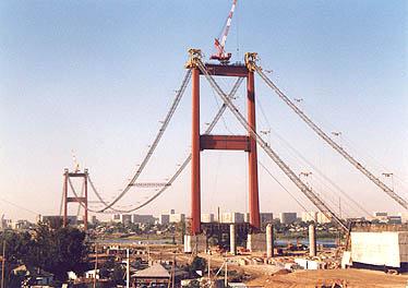
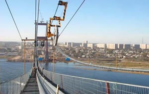
The AS method is used for cable fabrication by spinning wheels that travel across the top of the towers to the opposite anchorage and back carrying the individual strands. The wheels are hanging on a continuous hauling rope, carried along a provisional path of the main cable by an overhead cableway between opposite anchorages. The hauling rope carries the wheels over temporary suspended walkways, called the catwalk. The catwalks follow the curve of each cable, and are made of a set of guide wires, wire grate and wood slats (fig.15.1c). Special winches mounted atop the towers hoist them into place (fig. 15.1a). Ironworkers, who must see to the process of cable forming, work on these walkways.
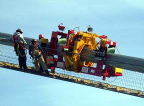
Each spinning cycle begins with placing a large spool of high-strength steel wire at the anchorage. The gauge of wire coated with corrosion inhibitors is typically 5 mm. First the wire handlers take the free end of this galvanized wire, make a loop, place it around a strand shoe and fix it to the anchorage. Then they make another wire loop, and place it around a grooved spinning wheel. The wire, held back by the anchorage, comes off the bottom of the wheel, laying on the catwalk. It is the dead wire. The wirethat comes fromthe spooland passesover the wheelis the live wire. The spinning wheel shuttles back and forth and spins the continuous cable strand by laying parallel wires. The wires are laid down on the tower top saddles equipped with rollers that allow free sliding of the main cables under live loads.
When the spinning wheel arrives at the anchorage, the crewmembers receive it and pull the wire loop from the wheel. They lay down the wire on the splay saddle, and connect it wire to the anchorage. The number of anchorage strand shoes is equal to the number of strands in the main cable, and all wires of each strand are attached to the same strand shoe. Then the workers send the wheel to the first anchorage to lay a fresh strand. They repeat the process until they have the necessary number of wires in a strand.
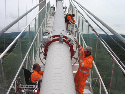
The ironworkers bundle the parallel wires into cable strands, and keep the strands together by taping or strapping them at appointed intervals. When the cluster of successive strands reaches the designed thickness, the crew removes the wraps from the individual cable strands and arranges compactor devices that squeeze the strands together to form the main cable (fig. 15.1c). The compactor compresses the strands into a closely packed cylinder throughout their length except at saddles and anchorages where the strands are separated.
The ironworkers also mount steel clamps called "cable bands". They aremade of paired semicylindrical steel castings, and mounted at predetermined locations at anchoring points where the vertical cables connect the bridge deck to the main cable with clamping bolts. Eachvertical or suspender cable has its preciselength and is looped over its cable band or connects a shackle-type fitting. The ironworkers coat the main and vertical cables with several layers of protective (fig.15.1d).
Finally, having attached the suspender cables to the main cables, the crew starts to build the superstructure. Travelling cantilever derricks move on the deck extending it in the opposite directions from the towers. Barges carry prefabricated deck segments to the site, and a moving crane, rolling atop the main cable, lifts them into place. The crewmembers connect deck segments to existing sections and secure them to the suspender cables.
The Pre-fabricated Parallel Wire Strand method uses full-length, prefabricated strands. First, the workers attach a pilot hauler rope to each anchorage to suspend the catwalk. The pilot hauler rope for the Akashi-Kaikyo Bridge was placed over the tower tops by helicopter. To fabricate each main cable, the builders transported each strand to the construction site, pulled each strand from one anchorage over the saddle of each tower, and then fastened that strand to the anchorage on the opposite shore of the Akashi Straits. They repeated that procedure 289 times, and then a cable-squeezing machine compressed the parallel wire strands into the main cable.
Barges transported the panels of the stiffening truss girder to the site, where traveler cranes lifted and transported them to the position, and the workers connected them to the suspenders. Lifting machines and equipment provided high-speed mounting due to 24 hours seamless operation. Finally, the main steel stiffening truss was attached to the main cable by suspender cable hangers.
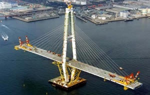
As the cable-stayed bridge requires less steel cable and offers all the advantages of the suspension bridge, but at a lesser cost for spans up to 1,000 meters, at present it is a popular choice. The cable-stayed structure offers great stiffness with little building material, and looks very elegant. Usually it does not require anchorages because the cables connect the roadway with a single tower that alone bears the weight and resists compression forces. Depending on bridge design, stay cables can carry the bridge deck from one or both sides of the supporting tower transferring all bridge loads to the foundations. Free cantilevering method is suitable forconstructing cable-stayed bridges. This method is economical because the precast or cast-in-situ deck segments can be assembled by travelling shutter arrangement.
| 
|
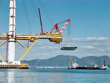
| a - Balanced cantilever erection method | b - Cantilever erection of main girder |
| |
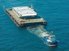
| c – Girder sections are delivered by barges |
Figure 15.2 Balanced cantilever erection method for construction of cable-stayed structures
The similar towers and hanging roadways of the cable-stayed bridge, at first glance, look like a variant of the suspension bridge, but their deck structures are unlike each other. The suspension deck, merely hanging from the suspenders, resists bending and torsion that can develop under live loads and aerodynamic forces. Construction of the suspension bridge deck cannot be started until the cables are entirely complete, but each span of a cable-stayed structure can be built out in stages from each tower (fig.15.2). The barges, which deliver the girder sections (fig. 15.2b,c), are exactly defined and positioned by GLONASS, a Russian global satellite navigation system.
Дата добавления: 2015-01-26; просмотров: 1826;