After reading the text, prove the idea that suspension structures are the safest among bridgeworks
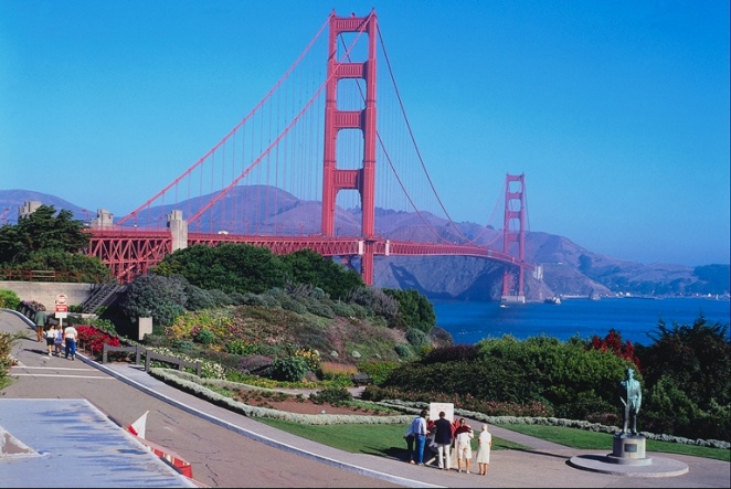
Early people developed one of the oldest engineering forms, known as suspension bridges. They mounted the roadway directly on cables made of vines (fig. 10.1a). Suspension bridges are light, aesthetic, graceful and easily constructed with materials, which builders can readily transport. Besides, there is no danger of failure during erection because the principal carrying member - the cable – easily endures overstressing. Using cables with relatively small dead weight, it provides an economical solution to the problem of long spans over navigable streams or rivers (fig.10.1b). Since the cables are in tension, they are the most highly efficient load-carrying component. Besides the economic considerations, the suspension bridge has many other points of merit.

| 
|
| a - The Earliest Suspension Bridges | b - The Golden Gate Bridge, the USA |
Figure 10.1 Suspension Bridges
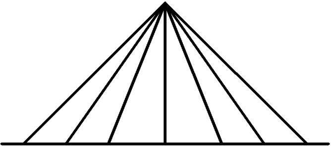
The structure with the supporting cables or stays connected directly to the bridge deck without any suspenders is a cable-stayed bridge. The basic systems of cable arrangements are radial or converging, harp, fan and star cable systems. When the builders anchor all cables to a common point at the tower top, the cable system is radial (fig. 10.2a).
| 
|
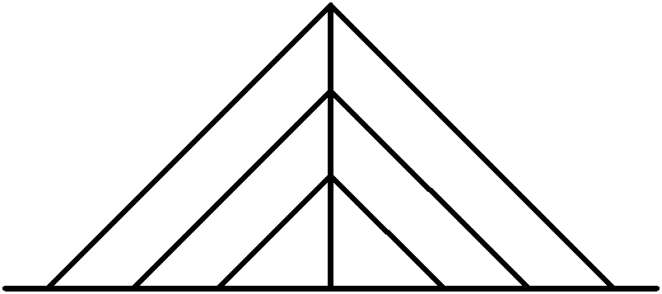
| a – radial pattern cable system with all cables anchored to a common point at the tower top | b - harp pattern cable system with parallel cable-stays |
| 
|
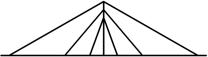
| c – fan pattern cable system with non-parallel cable-stays | d – star pattern cable system with cables descended at different heights and convergedat common points of the deck |
Figure 10.2 Diagram of Cable Arrangement in Cable-stayed Structures (геометрические схемы вантовых мостов)
If the cable arrangement looks like harp strings since the cables run in parallel and have equal distances along the tower height and between the neighboring points where they are attached to the superstructure, the bridge has the harp cable system (fig. 10.2b). The radial and the harp systems may be combined resulting in the fan-type cable system. In this case, the cables descend from the top of the tower at equal distances as in the harp cable system, and are attached to the superstructure at larger distances (fig. 10.2c). This arrangement is widely used, as it is, structurally, the most effective. The star system looks rather extraordinary as the cables descend from both sides of the tower at different heights. Then they convergeat common points, and are attached to the deck at the opposite sides of the tower (fig. 10.2d).
The suspension and cable-stayed bridges are often confused as, at first glance, they may look similar, but actually, they are quite different. However, both structures have very much in common - stiffening girders or trusses, anchor supports and cable hangers, their main bearing members are different in shape.
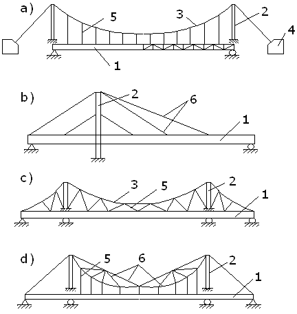
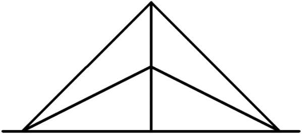
Figure 10.3 Diagram of Suspension and Cable-Stayed Bridges (висячий и вантовый мост)
a – Suspension Bridge (висячий мост); b - Cable-Stayed Bridges (вантовый мост);
c – High Stiffening Suspension Bridge (висячий мост повышенной жёсткости);
d - Cable-Stayed Truss (вантовая ферма)
1 – Stiffening girder (truss) (балка [ферма] жёсткости); 2 – Tower (пилон);
3 – Flexible Cable (гибкий кабель); 4 – Anchor (анкерная опора);
5 – Suspender (подвеска); 6 – Cable Stay (ванта)
The usual form of suspension structures consist of flexible cables passing over two towers. The cables are anchored to a steady foundation. The roadway is suspended from the cable by hangers. The main carrying element of a cable-stayed system is a straight cable (fig. 10.3; 10.4).
The two following criteria determine the difference between these two bridge types:
1. A suspension structure has curved steel cables or chains (fig.10.3a; 10.4a).
2. A cable-stayed structure has straight cables (fig.10.3b; 10.4b).
| 
|
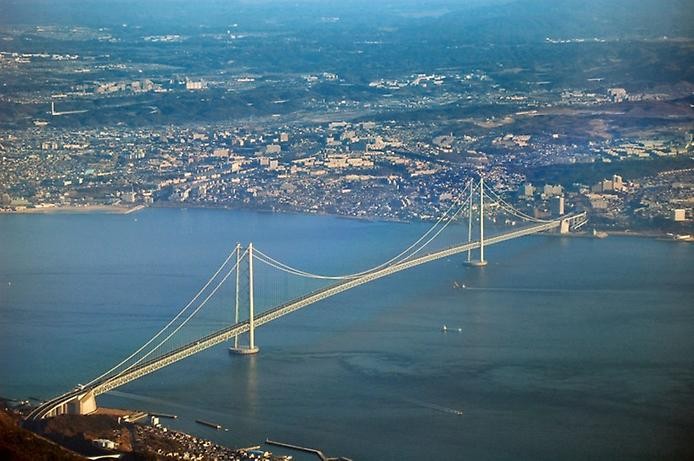
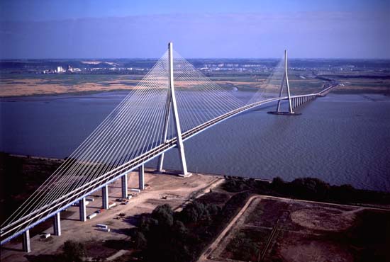
| a – Suspension Bridge (The Akashi Kaikyo Bridge, Kobe, Japan) | b – Cable-stayed Bridge (the Normandy Bridge) |
Figure 10.4 Suspended Bridge Structures
Modern bridge engineering uses the suspension span model at the large scale. The Akashi Kaikyo Bridge (fig.10.4a), now the world’s longest suspension bridge, crosses the strait with a main span of 1,991 m and side spans of 960 m. Two 297 m high towers, made of two hollow steel shafts connected by X-bracings, are the tallest bridge towers in the world. The cables are made of high-strength steel developed for the project by Japanese engineers. In 1995, an earthquake had its epicenter almost directly beneath the nearly completed Akashi Kaikyo structure; the bridge survived undamaged, though one tower shifted and lengthened the main span by almost one metre.
There are some types of suspension bridges without anchors. Their main cables are directly attached to the girder at both ends thus forming self-anchoring suspension structures.
The basic advantages of suspension and cable-stayed structures over other bridge types are:
1. The possibility to span very long distances from 500 m up to 1,990 m.
2. Construction by simple materials such as wood and common wire rope.
3. Less material may be required even at long spans. It results in reducing of construction cost.
4. High efficiency of these structures is due to the weight of the span per square metre, which is considerably less in comparison with other bridge systems.
5. The installation of the initial temporary cables allows a waterway to remain open for navigation while the bridge is under construction.
6. Suspension bridges may withstand earthquake movements much better than other bridge types.
7. Suspension and cable-stayed bridges often have merits that are more aesthetic than heavier and more rigid bridges.
The disadvantages of suspension and cable-stayed structures compared with other bridge types are:
1. Low vertical stiffness, i.e. the structure strongly exhibits high deflections under live load especially due to railway traffic because of the low deck stiffness.
2. Low horizontal stiffness, i.e. the structure exhibits considerable deck vibrating and displacement in a horizontal plane by wind force.
3. High sensitivity to dynamic and aerodynamic forces.
4. Some access below a suspension structure may be required for lifting the initial cables and deck segments, though this disadvantage can often be avoided in case of cable-stayed bridges.
To ensure high performance of suspension and cable-stayed bridges and prevent the deck from moving excessively under loading, the following factors are paid attention to:
1. Only high-strength steel wires with a rated resistance of 10,000 MPa are used.
2. Stay cables should be loaded only in tension because working in compression may result in suspension bridge collapse.
3. No weakening in suspension bridge cable is allowed.
4. Cable hangers and stay cables support the stiffening girder at many sites.
5. The stiffening girder transmits its dead weight to the cable and the towers. Such girder’s behaviour is due to the special construction technique.
The stiffening girders distribute the load in the span and prevent distortion of the deck. To make the stiffening girder lighter the planers use the force regulation in stay cables. This results in the most acceptable distribution of force. Each suspension structure is unique and designed with due consideration for both function and aesthetics. Currently bridge engineers construct striking suspension structures that are more efficient and less bulky owing to new building materials.
Modern technologies have heavily instrumented suspension bridges with measuring devices for determining vehicular weight or environmental characteristics including temperature difference, wind speed, etc. A global positioning system (GPS) is able to monitor the movements of suspension bridges with a high accuracy.
Дата добавления: 2015-01-26; просмотров: 2476;