Read the text and pay attention to the differences in the various techniques of superstructure construction
The variety of superstructure construction methods is rather wide. Each selected method depends on site constraints, height above ground or water, the type of span, span length, building material, architectural requirements, etc. The length of the span determines construction methods. For short and intermedium spans, the choice of construction methods is very wide. Long spans are restricted to continuous through girder or cantilever through girder. The only suitable form for extremely long spans is a stiffened suspension bridge.
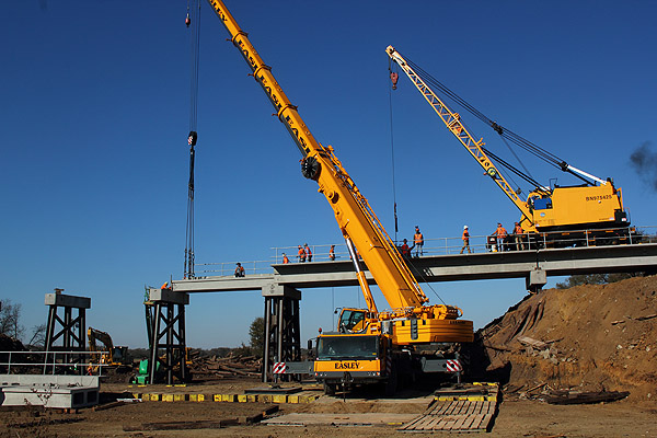
The simplest construction technique is conventional lifting used for single beam spans. Standard steel and reinforced concrete beams are shipped to the site, and the cranes place them in design position (fig. 14.1a; 14.2a) parallel to each other (fig.14.1b). They are covered with slabs and concrete. When a bridge is a continuous one, each simple beam resting on two supports is sequentially joined to the next one and forms a continuous beam (fig. 14.1).
| 
|
| a – Superstructure erection by crane (монтаж пролетного строения краном) | b – Standard beams are placed to each other and covered with floor beams |
Figure 14.1 Superstructure Construction by Conventional Lifting
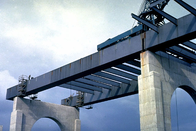
Usually concrete segments or plate girders, called I-beams, are suitable for long spans. They consist of deep vertical webs with top and bottom chords welded or bolted to the webs. To reduce bending at the middle of a longer span, bridge engineers use haunched beams with a cross section that is shallower at mid-span and deeper at the supports. Extremely heavy precast segments may be hoisted using hydraulic lifting techniques.
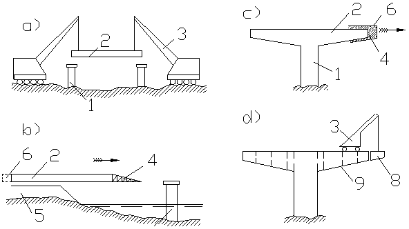
Figure 14.2 Superstructure Construction (монтаж пролётного строения моста)
a – Erection of Discontinuous Beam (монтаж разрезных балок); b – Erection by launching (продольная надвижка); c – Balanced concrete casting (навесное бетонирование);
d – Balanced cantilever erection (навесной монтаж).
1 – Pier (опора); 2 – Beam (балка); 3 – Crane (кран); 4 – Launching Nose (аванбек);
5 – Embankment (насыпь); 6 – Travelling Shuttering (передвижная опалубка);
7 – Poured Concrete (уложенный бетон); 8 – Superstructure Block (блок пролётного строения); 9 – Juncture (шов)
Superstructure construction methods use various construction machineryincludingstationary or travelingfalseworkand temporary towers. Falsework determines the shape of arches or bridge shapes with geometrically complicated alignments. Temporary towers provide additional support for a superstructure during its building up. Commonly, there are three major erection methods - balanced cantilever construction (fig. 14.2d), balanced concrete casting (fig. 14.2c) and incremental launching (fig. 14.2b) employed in bridge superstructure construction along with a wide range of different adapted techniques.
| 
|
| a - Erection of continuous beam by incremental launching (продольная надвижка неразрезной балки) | b – Cast-in-place cantilevering (метод навесного уравновешенного бетонирования ) |
| 
|
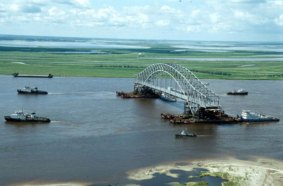
| c - Erection by floating into position (монтаж пролётного строения методом «на плаву») | d – Semi arch erection afloat (монтаж полуарок «на плаву») |
| 
|
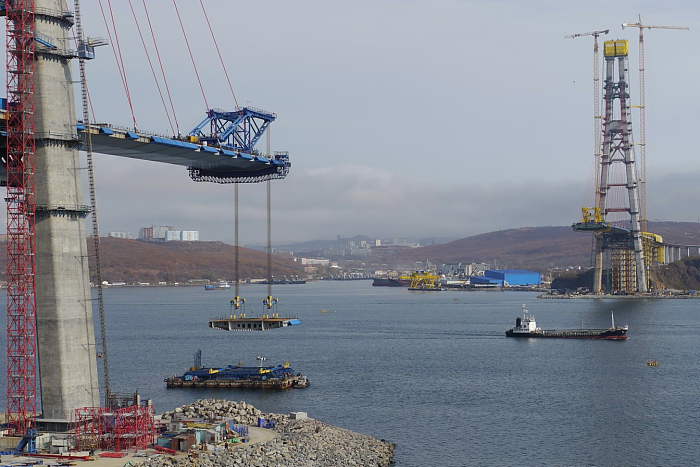
| e – Superstructure erection afloat (монтаж пролетного строения «на плаву») | f - Steel arch is being lifted simultaneously with supporting (арка поднимается одновременно с сооружением опор) |
Figure 14.3 Various construction methods for superstructure erection
Incremental launching is a highly mechanised construction method. It is specifically suited for multi-span superstructures for very long gaps spanned by reinforced concrete continuous girders. These post-tensioned girders, cast on the bank behind one of the abutments, are from 15m to 30 m long. They are cast over a casting bed in a stationary formwork. Then cured and ready girders are pushed to the final position (fig. 14.2b). Each sufficiently hard newly cast segment is launched along the bridge axis in small increments with hydraulic jacks or by temporary sliding bearings. As the length of segments is long, and reinforced concrete has rather high density, builders use a launching nose attached to the cantilevering segment. The launching nose reduces the bending moment in the girder (fig. 14.2b; 14.3a).
This erection method has numerous advantages such as falsework elimination, reduced investment for special equipment, etc. However, it also has certain disadvantages, which limit its use: the concrete has to be prestressed in advance, and it needs time to reach a required density. Besides, the stationary casting bed cannot allow large changes in superstructure curvature.
Two cantilevering methods - cast-in-place cantilevering and balanced cantilever construction are suitable for framed suspended bridges, flyovers and trestles. Both fashions of cantilevering by building up new segments are very advantageous for bridging even inaccessible natural barriers.
Cast-in-place cantilevering or balanced concrete casting employs travelling shuttering for mounting the cast-in-situ segments that may achieve the length of 5.00 m (fig. 14.2c). The mobile frame, attached to the cantilever tip, supports the formwork with the newly cast segments. The mobile frame moves within the existing portion of the superstructure and constructs cantilever arms on either side of the supports. It stays in place until a newly cast segment gains sufficient strength, and then it moves forward. Normally, the duration of a casting cycle is about a week. In-situ concreting advances symmetrically, and finally cantilever arms connectd at midspan. The important advantage of this metod is that it leaves the waterway or valley beneath the bridge unobstructed during the superstructure construction.
Structures of intermedium and long spans require cantilevering method, known as a balanced cantilever construction,when the erection of scaffolding is unfeasible due to site constraints. Cable-stayed bridges are ideally appropriate for construction by segments, prefabricated in casting yards. They are transported to the construction site where the workers mount them by gantry cranes or by mobile equipment, such as swivel cranes, fixed to the deck (fig. 14.3c).
As a rule, the superstructure construction starts from short stubs on top of piers, and proceeds symmetrically forming cantilever arms toward the midspan. The segments are stuck together with an epoxy adhesive or cement. This construction method leaves no possibility for later correction, and the workers fix segments exactly in the right position. Once cantilever arms are completed, they place the closure segment between them to construct a continuous superstructure.
Cantilever span may have either two arms proceeding from both sides of a pier or only one arm increasing from its abutment or on one side of a pier. When two cantilever arms are balanced in a scales-like fashion, cantilevering requires Balanced Cantilever Construction. The second type of cantilever system consisting only of one arm requires the Progressive Placement Method. In this case, the superstructure may need temporary towers.
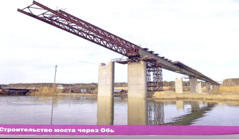
A launching truss or launching girder is a different type of construction equipment forplacinginto positionthe set of precast segments or for castingsegments at opposite sides of the same pier. Thelaunching truss propels itself forward assembling the superstructure span-by-span. Thismethod is suitable for multi-span bridges when scaffolding is not feasible due to site constraints or difficult terrain conditions. The length and configuration of launching trusses provide a very high speed of construction.
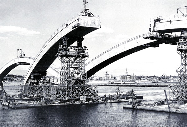
Arch bridges require rather complicated construction technology. The traditional method demands temporary piers and arch centering to reproduce the shape of the arch superstructure (fig. 14.4a). The precast reinforced concrete segments are placed on an arch centering.
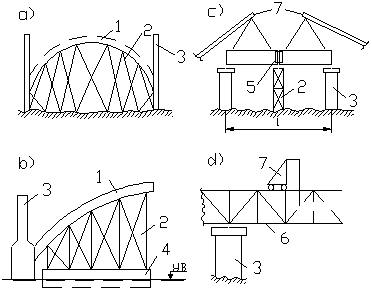
Figure 14.4 Superstructure Construction
a – Arch Erection by Arched Falsework (монтаж арки на подмостях); b - Arch Erection Afloat (монтаж арки на плаву); c –Long Beam Erection (монтаж длинных балок); d – Erection of Trussed Girder (монтаж сквозных ферм);
1 – Arch (арка); 2 - Arch Centering (кружала); 3 – Pier (опора); 4 – Pontoon (понтон); 5 – Block Junction (стык блоков); 6 – Trussed Girder (сквозная ферма); 7 – Crane (кран)
The cast-in-situ concrete arch is erected in a curved framework. The construction of arches above water is a much more advanced technique. The arches and semi-arches are assembled on the bank and transported to a barge, which carries these structures to the place (fig. 14.3d,e).
Дата добавления: 2015-01-26; просмотров: 2371;