Read the text about the most astonishing British bridges and tell about them 4 страница
A circular plate is the rotating cutting wheel,called arotating boring head or a cutter head. It is covered with tungsten carbide cutting bits including milling cutters, disk cutters, steel rotating disks ora combination of the three.
The cutting edge grinds the hard rock or slice into soil in the tunnel face by chisel-shaped cutting teeth. Some obstructive inclusions or head-on collision with boulders can damage the cutting edge, and the TBM’s personnel remove or replace the individual segments. In most favorable soil, as it was in the Chunnel, the circular platecan rotate more than 10 revolutions per minute.
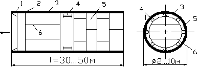
Figure 19.3 Tunnel Shield Structure (конструкция проходческого щита)
1 – Cutting Edge (ножевое кольцо); 2 Non-Rotating Stabilizing Device – (опорное кольцо);
3 – Steel Skin (стальная оболочка); 4 – Shield Jacks (домкраты);
5 – Precast Segments (готовые тюбинги); 6 – Bulkhead (перегородка)
The TBM’s structure also includes a back-up systemconsisting of trailing support decks (fig. 19.1). The back-up system include control rooms for operators, break-time space for workers, conveyors and slurry pipelines for tunnel muck removal, firefighting equipment, electrical support equipment, ventilation and dust removal systems. The rock, excavated by TBMs, passes through spaces in the rotating boring head onto a belt conveyor, which carries it through the shield to the rear of the machine where it drops into muck carrying vehicles for removing it from the tunnel.
The shield diameter may range from one to 10 m and its total length may reach up to 30 or even 50 m (fig. 19.1). Large diameter TBMs allowed the construction of bi-directional rail tunnels. Massive robotic arms, mounted at the rear of some machines, raise lining segments to the final location as soon as the shield has advanced at sufficient distance. To propel the shield forward through rock, the gripper arms extend outward from its sides and push firmly against the tunnel walls. Using hydraulic cylinders, they propel the shield at the predetermined distance, or hold it in place for keeping the cutter head in contact with the tunnel face while cutting it.
The shield diameter may range from one to 10 m and its total length may reach up to 30 or even 50 m (fig. 19.1). Large diameter TBMs allowed the construction of bi-directional rail tunnels. Massive robotic arms, mounted at the rear of some machines, raise lining segments to the final location as soon as the shield has advanced at sufficient distance. To propel the shield forward through rock, the gripper arms extend outward from its sides and push firmly against the tunnel walls. Using hydraulic cylinders, they propel the shield at the predetermined distance, or hold it in place for keeping the cutter head in contact with the tunnel face while cutting it.
Shielded hard rock TBMs work in hard or fractured rock. The Double Shield TBM with two modes of operation is applicable both in stable and unstable ground (fig.19.5a). One operation mode, used in stable ground, allows these TBMs to advance by gripping against the tunnel walls. The other operation mode is for unstable, fractured ground where the TBMs advance by thrust cylinders. They push off against the most recently installed tunnel segments that protect the fragile tunnel walls.
| |
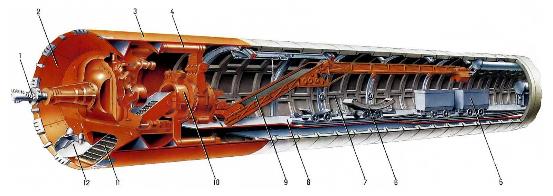
| a - Tunnelling shield with main bearing (щит проходческий со штанговым рабочим органом) : 1 – cutting wheel (рабочий орган); 2 – cutting head (ножевая часть щита); 3 – skin (shell) (корпус щита); 4 – shield jacks (домкрат-передвижки); 5 – muck-carrying vehicle (вагонетка); 6 – segment-carrying vehicle (блоковозка); 7 – segmental lining (обделка); 8 – trailing backup system for muck and material transportation, ventilation, power supply, etc. (технологическая платформа); 9 – belt conveyor (ленточный конвейер); 10 – erector (блокоукладчик); 11 – scraper [пластинчатый (скребковый) конвейер]; 12 – muck chamber (погрузочное устройство) | |
| 
|
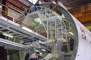
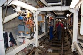
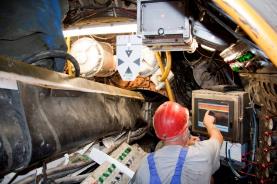
| b – Workers ansembling a TBM in a launching chamber | c – Workers operating a TBM within a tunnel |
| 
|
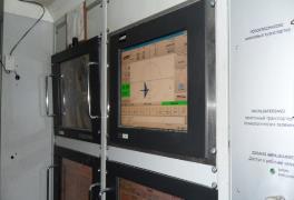
| d - Devices and instrumentation for TBM operation |
Figure 19.4 TBM Body Structure
The Single Shield TBM (fig.19.5b), that is applicable only in fractured ground, provides three operational modes (open, semi-pressurized and pressurized). These TBMs advance by pushing off against the concrete segments that are already in place and joined.
| 
|
| a - Double Shield TBM – щит “телескоп”, двойной щит | b - Single shield TBM (“единый” щит): 1 - shield; 2 - thrust cylinders; 3 - segmental lining; 4 – cutting head; 5 muck bucket (приёмник породы); 6 - conveyers |
Figure 19.5 Shielded hard rock TBMs
Modern tunneling employs either an open-face type or closed-type machines. The "head" parts of the closed-type machines are "closed" and separated from their rear parts. These machines are known as EPB (earth pressure balanced) and SS (slurry type shield machine). To advance forward both of them are equipped with thrust cylinders that push off against concrete segments.
The EPB type shield machine (fig. 19.6) is suitable in soft ground because it can maintain the balance between earth and the backpressure. This gave it its name. This machine may be applicable for clay soil with less than seven bar of pressure, and is not suitable for hard rock because the excavated soil is difficult to be turned into slurry. To counterbalance the cutting face under soil and water pressures in front of the TBM, the "head" part is equipped with an excavation chamber between the cutting face and bulkhead. Soil or slurry enters the excavation chamber during the boring process. Mud pressure in the excavation chamber stabilizes the cutting face and holds it under soil pressure. The TBM operator keeps the soil pressure at a constant value by automated control system that helps to balance the rates of soil discharging and machine advancing. One or two screw conveyors transport the soil away from the cutting head to the conveyer belt.
|
| Earth Pressure Balance Machine (щитовой проходческий комплекс с грунтопригрузом): 1 – Cutting head (ножевая часть щита); 2 - Excavation chamber (приёмник породы); 3 – Bulkhead (перегородка); 4 - Thrust cylinders (домкраты); 5 - Screw conveyor (винтовой конвейер); 6 - Segment erector (блокоукладчик); 7 - Segmental lining (обделка) |
Figure 19.6 Earth Pressure Balance Machine
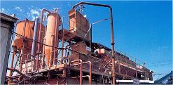
The Slurry Shield (SS) is suitable for soft ground saturated with large amounts of ground water under very high pressure (fig. 19.7a). It can operate below the water level due to the pressurized compartment at its front end. The SS has slurry feed line and removal equipment for pressurizing and circulating slurry. It balances the water pressure by the external pressurized slurry that stabilizes the tunnel face ahead of the cutter head. If the soil surface is not workable enough the bentonite slurry is pumped into the cutting head where it is mixed with the excavated soil that is transported by fluid conveyance done by circulating mixed slurry. The mixed slurry is pumped out onto the surface through slurry tubes. Then it is separated again into the bentonite and dirt at slurry treatment plants (fig. 19.7b). Next, it is recycled back into newly excavated soil in the tunnel face. The room behind the pressurized compartment, where the operator works, has normal air pressure and a totally enclosed working environment.
Open face TBMs are used either in hard rock or in soft ground with low water inflows or if the tunnel face is able to stand up without support for a short period of time while being excavated. The open-type machines do not put concrete lining. The workers install ring beams and steel straps, spray shotcrete or secure rock bolts and wire mesh to hold up the rock.
| 
|
| a - SS type machine [щитовой проходческий комплекс с гидропригрузом (с гидротранспортом породы)]: 1 – Cutting head; 2 - Excavation chamber (герметичная призабойная зона); 3 – Bulkhead; 4 - Slurry feed line (подача гидропригруза); 5 - Air cushion; 6 - Wall; 7 - Segmental lining; 8 - Segment erector | b - Slurry treatment plant |
Figure 19. 7 Technological Process by the Slurry Shield Complex
Though shields require considerable time for setting-up, they are easily operated and ensure an accurate breakthrough when they dig toward each other from opposite tunnel ends in hostile ground environment. The TBM operator uses control systems to avoid any wobble and eccentric rotation of the cutter head because the diameters of the tunnel and the cutting head must be equal in sizes. Driving a smooth curve with a shield requires great skill and experience. It is costly or even impossible to withdraw shields from the heading. Each of the two opposite shields may dig a short spur to steer them away from the path of the tunnel for permanent sealing.
Shield tunneling has many advantages; however, it has some disadvantages as well. First, there are non-mechanical shields and the workers have to use hand tools for loading the muck or placing the lining segments. Second, only small shields are assembled in the shop and. They are shipped to the job site in one piece. Most shields are assembled in situ, at the tunnel portal or at the bottom of the launching shaft. Assembling, starting and dismounting the shield in situ require a special mounting platform, and are very expensive and labour consuming operations.
Civil engineers consider shields to be a promising area of improvement. They have devised multiple-headed TBMs for simultaneous boring of two or three parallel tunnels (fig.19.1b). Recently built shields are able to turn a corner up to 90° during a tunnel boring operation. The necessity for drilling core samples and boring probe headings ahead of tunnel face has been also reduced due to a virtual CAT scanning that is generated by sound waves which are transmitted through the earth. The trend in TBM design is towards remote control systems. It will improve workers’ safety and reduce the working time in the underground space.
GENERAL IDEA OF THE METRO
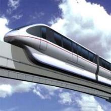
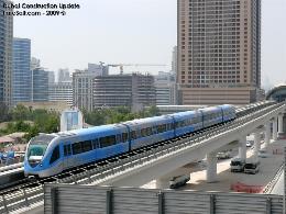
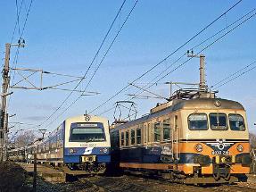
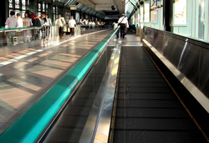
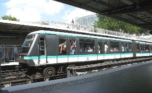
The metro is a version of rapid transport of people comprising different modes of public transport like light metro, monorails and people movers (fig.20.1). In some cities in Germany, Austria, Switzerland and Denmark passengers travel by the fast metro-like railway line known as S-trains or S-Bahn which is a hybrid exhibiting features of both commuter rail systems and rapid transit.
| 
|
| a - Monorail | b - Elevated Metro Line |
| 
|
| c - the S-trains can travel by usual railway tracks | d – People Mover (Moving Sidewalk) Перевозка людей на короткие расстояния |
Figure 20.1 Rapid Transport Systems
The metropolitan known as subway or underground is the electric underground railway system with frequent station stops for fast transportation of large numbers of passengers in large cities. The metro runs through underground tunnels but it also may be elevated above street level on trestle bridges (fig.20.1b). For instance, the S-Bahn uses either underground or elevated tracks within the city centre, and can travel by usual railway tracks to suburbs and nearby towns.
Currently nearly 160 metropolitan areas all over the world have a metro system. The underground system in our country extends only within the city limits but in many foreign cities, it reaches outer suburbs by commuter rail networks. A synchronized timetable, electric locomotives and train doors at platform level allow the trains to use the railway lines (fig.20.1c).
The metro all over the world uses different types of line arrangement and may consist of one or several lines. Sometimes, lines can share tracks with each other. Some foreign metros use grade-crossing lines (fig. 20.2d), and each line has individual names, colours or numbering. For instance, the Paris Metro has a unique structure, arranged as crisscrossing lines with very densely spaced stations in the city core. The Prague Metro also has numerous interchange stations in the city central area. The Copenhagen Metro provides a high service frequency in the central city areas, and running through the city streets, it forks into suburb branches. The London Tube and the Moscow Metro are far-reaching underground rail systems with loop lines that connect the outward metro lines. Some underground railway systems share their central terminals with the city central railway station.
The metro lines in Russia are laid in different levels providing a safe service without any risks for train collisions. It is an effective way to travel within the city because buses, trolleybuses and tram routes or even commuter rail network run near metro stations. By traveling with underground system, passengers can get to their stop without changing trains or transfer between lines at interchange stations using connecting subways. Transit maps or schematic diagrams at stations and in cars show the line routes and stations. The lines are colour coded and the stations have their named icons. Regular audio announcements about the arriving trains also help passengers along with visual platform displays, boards and direction signs on the station walls. In Hong Kong the MTR passenger railway system provides bilingual real-time information on every platform.
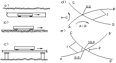
Figure 20.2 Diagram of the Metro Lines (схема линий метро)
a – Underground Lines (подземные линии); b – Ground-level Lines (наземные линии); c – Elevated Lines (надземные линии);
d – Underground Lines crossed at the same level (пересечение линий в одном уровне);
e – Underground Lines crossed at didderent levels (пересечение линий в разных уровнях).
1 – Underground Lines (линии метрополитена);
2 – Underground Passage (подземный переход)
The advantages of the metro are its high speed, shorter headway and higher capacity in transporting large numbers of passengers. In addition to other beneficial effects, the metro settles the problems of traffic jams, air pollution and noise. The London Underground, opened in 1863, clearly demonstrated these advantages. The idea spread all over the world and not only to other European cities but to the United States and Asia, especially to China. The rapid growth of traffic flow in modern cities has given rise to the swift expansion of the metro because the drivers and passengers, who daily waste their time in traffic congestion and lose their health and even lives in daily traffic accidents, want safer, faster and top-quality services. The expected growth of chronic hold-ups and bottlenecks in city streets, continual and sharp increase in fuel prices makes the owners of private cars travel by public transport, and mega-cities see the metro as a sustainable means of mobility. Currently many countries are developing their underground transit networks though their construction, within the city areas, is a rather complicated and expensive engineering work.
In our country, the metro differs from the railways by the track gauge, and the current collection devices. It provides its service on rails between stations using the power delivered either by a third rail or by overhead wires where the metro line is at ground level, for instance, at the terminal stations (fig.20.3d).
| 
|
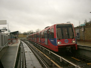
| a – Subway train-set using rubber tires | b - Driver-free train-set at ground-level line (поезд с автоматическим управлением на наземной линии метро) |
| 
|
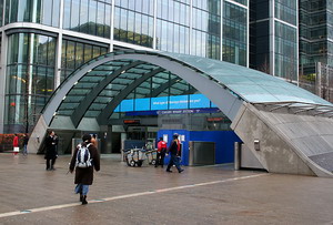
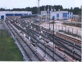
| c – Metro Street Facility (наземный вестибюль) | d – Depot (депо) |
Figure 20.3 Metro Rolling Stock and Facilities
Metro trains are multiple units with three or more cars per train that can accommodate a large number of people (fig. 20.3a,b). S-Bahn uses bi-level carriages that are more spacious and allow better seating areas for passengers. The transit capacity of metro lines depends on the service frequency, the number of passengers, accommodated in cars, and train-set length. The car capacity ranges from 90 to 270 passengers per car, and the ratio of seated to standing passengers may be varying. The MTR Corporation in Hong Kong attains its highest capacity of 80,000 people per hour. The headway is much shorter compared to other modes of public transit system and ranges from ninety seconds to six minutes.
The idea of the innovative underground railway system has been developing by a part of the London Rail division of Transport for London known as Dockland Light Railway. DRL involves several ground metro lines with the fully computerized signaling system. It operates the driver-free train-sets guaranteeing a safe distance between them. The sustem gives information about each train-set location, controls the fully automatic car doors and stops train-sets at stations. As there is no driver’s cab in the first car, the passengers use the front passenger seats immediately at the large and spotlessly clean car windshield (fig. 20.3b). However, the train-sets cannot manage entirely without 'drivers'. At certain stations, a uniformed Train Captain enters the car and, if required, takes manual control for the safe train travelling at difficult station spans. He or she also checks tickets and can give information or advice. Then the Train Captain leaves the car and the train returns to central computer-aided control. The platforms at all DLR stations have ramp or lift access. In case of experiencing any problems, the passengers can talk directly with a member of DLR staff as all lifts are equipped with enabled alarms. For easy access onto the trains, the open space between the train and the platform edge is no more than 7.5 cm. The steps from the platform to the train are 5cm in height. Passengers use standard travel tickets, monthly and seasonal tickets on these lines.
The Metro always provides stimulating competition to the surface transport system owing to its good service and safe, reliable and convenient passenger travel. Therefore, the metro is much more than a means of moving people around, it is also a prestige showcase in the face of the competition between cities.
THE NOVOSIBIRSK METRO
First proposed in the early 1960s, the Novosibirsk metro got official approval 15 years later. The project had a key role for the rapid transit in the city because fast and convenient public transport was crucial for the extended city areas on both banks of the Ob River. The negotiations lasted for several years, as the authorities of Novosibirsk could not make a choice between an underground railway and a high-speed tram. In 1968, government officials decided in favour of the metro, but the project required new approaches in engineering and financing. The Government of the USSR did not guarantee the financing until 1975. The Council of Ministers approved the project in 1978 after violent discussions and exchanging of ideas. They chose the deliberate engineering decision of the first metro section that included the part of the Lenin line from Zaelitsovskaya metro station to Marx Square metro station, and a section of the modern Dzherzhinsky line from Garin-Mikhailovsky Square metro station to Sibirskaya metro station. The project also included the construction of the Elitsovskoye depot for train-sets where they can be sheltered and dispatched for service.
The next step was to carry out the preliminary study and surveys. The planning organization “Novosibirskmetroproject” and the governing body of the future metro faced the challenge of planning, constructing and operating the first Siberian underground railway under severe climatic conditions. The launch stage included five stations between Krasny Prospect and Studencheskaya metro stations. Researchers and engineers from Siberian State University of Railway Engineering largely contributed to the work. The “Bridges and Transport Tunnels” Faculty is proud of its graduates and uppermost of M. Nemilostivykh, A. Melnik, V. Tour and many others who made a major contribution to building of the Novosibirsk Metro.
The geological conditions appeared to be rather favorable for constructing shallowly located stations. It reduced the price of the project and allowed for two types of station arrangement. Some stations are single span, and others are pillar- trispan. Each station has four entrance/exits either combined with the city underground passages or built in the nearby buildings. Sibirskaya metro station with a depth of 16 metres is the deepest, “Rechnoy Vokzal” metro station is the shallowest among all the stations.
The builders drove the first pile for Oktyabrskaya metro station on May 12, 1979. They used the cut-and-cover technique for the first line between Oktyabrskaya and Lenin Square metro stations. The tunnel was dug from the surface along the flood lands of the River Kamenka. Concrete lining supported that tunnel section. The further tunnel portion was driven through the rock. The tunnel required effective ventilation because many dumper trucks removed the muck from it.
The Siberian metro was built under severe weather conditions with 45 degrees Celsius below zero in winter, and was to withstand earthquakes of up to magnitude 6 on the Richter scale. The first building crews and units from Tashkent, Moscow, St Petersburg, Minsk, Gorky, Kharkov and neighboring Siberian cities together with Novosibirsk residents did their best to construct the metro in Siberia.
In 1980, the first TBM excavated the second tunnel between Oktyabskaya and Lenin Square metro stations. The first breakthrough took place on June 19, 1980 when the TBM, operated by the Tunnel Building Subdivision№ 29, cut through the rock and appeared in the trench of Lenin Square metro station within a high degree of accuracy, thanks to the excellent survey work. The drift miners broke into cheers looking at the shield. They successfully completed the very first one-kilometer experimental driving.
The driving within the city limits faced various serious problems. The threat of breaking in dwelling houses appeared in 1984 during driving of the left interstation tunnel between Oktyabrskaya and Lenin Square metro stations. Urgent actions for stabilizing the buildings prevented ruinous consequences, but seriously affected the time of the tunnel completing.
In August 1983, the first station was faced with marble, and in June 1984 the track was laid. The builders used the rail type known as P-65 (in Russian) that reduces the noise and vibration in tunnels. The service life of this rail type is much longer as compared to other types in use. Now the total weight of rails is more than 2,000 tons and each rail section length is 25 metres.
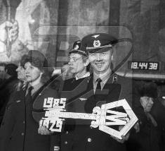
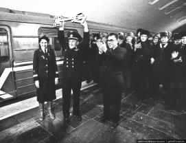
Opened with due ceremony in the presence of the city top-ranking officials, the first line was available for use by the public on December 19, 1985. It was a celebratory event, but the official opening ceremony of the Novosibirsk Metro took place on January 7, 1986 with the first trial-passenger service (fig.21.1). A year later a short shuttle line provided access to the city railway station at Garin Mikhailovsky Square. This station is named after one of the founders of our city who was a talented Russian engineer and writer. In 2007 the facade of the Novosibirsk Metro Administration Building was decorated with the memorial plaque devoted to the first chief of Siberia’s Metro Yu. S. Lelekov, the Hero of Socialist Labour, awarded the Lenin Order, the Order of Red Banner and the Award of Honour, the highest rank awards in the USSR.
| 
|
| a - Symbolic Key to the Novosibirsk Metro presented by the builders | b - The memorial plaque devoted to the first chief of Siberia’s Metro Yu. S. Lelekov |
| |
| c - The celebratory event of the Novosibirsk Metro official opening |
Figure 21.1 The inauguration ceremony on January 7, 1986
Gagarin and Zaelitsovskaya metro stations were added to the Lenin line in April 1992. It almost completed the first stage of construction. These stations were the only possible way for developing public transport on the right bank of the Ob River. This section faced unforeseen high levels of ground water. That problem called for new and quite different sorts of drains. Once passenger service began, the metro line was in operation 20 hours a day, seven days a week.
In December 2000, the second line, known as the Dzerzhinsky line, began its service to the station named after a celebrated fighter pilot Marshal Pokryshkin who was born in Novosibirsk. In June 2005 this line was extended to Beryozovaya Roshcha (Birch Grove) metro station, and in October 2010 to Zolotaya Niva metro station (Golden Grain Field). The Dzerzhinsky line operated with two shuttle services up Zolotaya Niva metro station was completed. The first shuttle service was regular between Garin Mikhailovsky and Sibirskaya metro stations; and another one was between Sibirskaya and Beryozovaya Roshcha metro stations. In 2007 the second tunnel between Marshal Pokryshkin and Beryozovaya Roshcha metro stations was put into operation.
| 
|
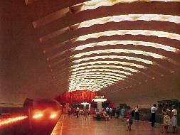
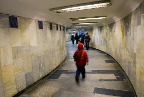
| a - Lenin metro station of the Novosibirsk Metro. | b - Underground Passage between stations |
| 
|
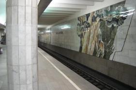
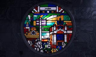
| c- Marble Panel showing Siberian Resources decorates ‘Sibirskaya’ metro station at the Dzerzhinsky line | d - Stained glass decoration at Rechnoy Vokzal metro station |
Дата добавления: 2016-01-03; просмотров: 1461;