Read the text about the most astonishing British bridges and tell about them 2 страница
The classification of concrete piers includes three groups according to construction technology:
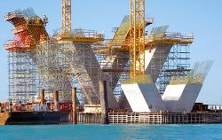
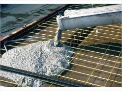
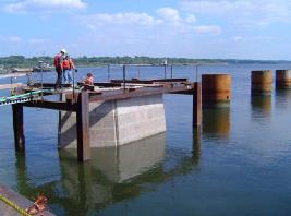
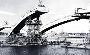
1. Cast-in-situpiers (fig. 13.1a; 13.2). The concrete is placed against the casing in situ. The casing determines the pier shapes and dimensions.
2. Precast piers (fig. 13.1b). The piers are made of prefabricated concrete blocks.
3. Composite piers (fig. 13.1c). These piers, built from the precast concrete units and in situ concrete, are used on a large scale.
| 
|
| a – Adaptable Falsework for Pier Geometry | b – Falsework used to support a structure during the construction of piers |
| 
|
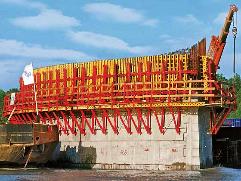
| c - Concrete is being conveyed into the casing in situ | d – Falsework and cast formwork for placing concrete built on precast concrete segments (Подмости и опалубка для бетонирования, установленные на сборных блоках) |
Figure 13.2 Technologies of Bridge Pier Construction using adaptable casing and falsework
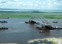
Bridge builders construct concrete arches in situ using temporary supporting casing. After the construction of abutments and piers, they provide a metal or wooden arch falsework, which holds the poured concrete, and later the workers remove it. For steel arches, they employ a cantilevering method. Each side of an arch is built out toward the other, supported by temporary cables until the ends meet. At this point, the arch becomes self-supporting, and the workers remove the cables or arch falsework.
To build foundations for bridge piers in a river, workers need a water-free environment for excavating trenches. They sink caissons filled with compressed air into the riverbed and work inside them. Caissons are large hollow timber, steel or concrete watertight boxes or cylinders with sharp bottom edges. When these structures reach the river bottom, the workers dig out sand and other bottom silt until they come to bedrock. The caissons, moving downward during the digging, finally rest on bedrock, and the workers fill them with concrete. Having poured concrete into the caissons the workers can build the lowest section of piers. In case of suspension bridges, towers are built atop the caissons.
| 
|
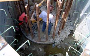
| a - Construction of Pier Footing | b - Precast concrete pier boxes for footings (Опалубка из сборных блоков для сооружения фундамента опоры) |
Figure 13.3 Preparation for construction of pier footings by placement of reinforcing (сооружение фундаментов опор с установкой металлической арматуры)
Bridge abutments and piers must be secure at the foundations in order to support the superstructure. The term “foundation” includes some elements placed in and on the ground to provide support. The methods of foundation construction may be vary to some extent and depend on geological conditions, ground strength, pier types and sizes, loads from the spans and piers. In case of especially weak or swampy soil, the workers drive wooden or steel piles into the ground to support the foundations. Then they cast concrete footings, wait for sufficient concrete hardening, and begin building piers and abutments (fig. 13.3).
Bridge foundations include two large groups: shallow foundations (fig. 13.1d) and deep foundations (fig. 13.1e, f, and g). Shallow foundations are usually monolithic structures on the natural bed. This technology is rather cheap and simple, but it is applicable for solid rock only (fig. 13.1d). The construction of shallow foundations begins with trench excavation. Rather deep trenches, excavated in a dry place for the abutments or piers of the flyovers, viaducts or trestle bridges, require a watertight enclosure or a sheet piling made out of metal bars. It is also necessary if a trench is excavated in a river (fig. 13.1d; 13.3a) as the bed must be pumped dry to permit the pier construction. A pile driver drives a sheet piling to the predetermined depth. Horizontal framing components constructed of heavy timbers, steel, or a combination of the two, hold the vertical piles in place. The structure must be able to resist the horizontal forces from the surrounding body of water when the inside water is pumped out. Then concrete is placed against the casing. The workers spread and compact it. The most difficult work is to pour the concrete for the foundations constructed in the river. Despite working water pumps, some water enters the trench, and the builders have to inject additional grouting mortar (fig. 13.1d) to consolidate the soil in the water.
SUPERSTRUCTURE CONSTRUCTION
The variety of superstructure construction methods is rather wide. Each selected method depends on site constraints, height above ground or water, the type of span, span length, building material, architectural requirements, etc. The length of the span determines construction methods. For short and intermedium spans, the choice of construction methods is very wide. Long spans are restricted to continuous through girder or cantilever through girder. The only suitable form for extremely long spans is a stiffened suspension bridge.
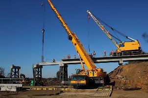
The simplest construction technique is conventional lifting used for single beam spans. Standard steel and reinforced concrete beams are shipped to the site, and the cranes place them in design position (fig. 14.1a; 14.2a) parallel to each other (fig.14.1b). They are covered with slabs and concrete. When a bridge is a continuous one, each simple beam resting on two supports is sequentially joined to the next one and forms a continuous beam (fig. 14.1).
| 
|
| a – Superstructure erection by crane (монтаж пролетного строения краном) | b – Standard beams are placed to each other and covered with floor beams |
Figure 14.1 Superstructure Construction by Conventional Lifting
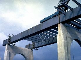
Usually concrete segments or plate girders, called I-beams, are suitable for long spans. They consist of deep vertical webs with top and bottom chords welded or bolted to the webs. To reduce bending at the middle of a longer span, bridge engineers use haunched beams with a cross section that is shallower at mid-span and deeper at the supports. Extremely heavy precast segments may be hoisted using hydraulic lifting techniques.
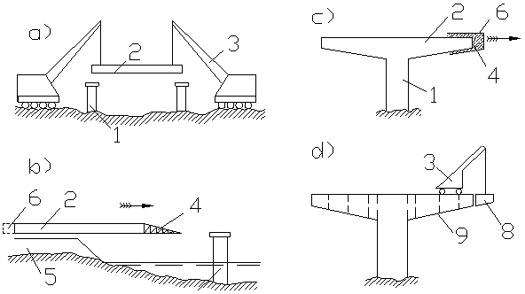
Figure 14.2 Superstructure Construction (монтаж пролётного строения моста)
a – Erection of Discontinuous Beam (монтаж разрезных балок); b – Erection by launching (продольная надвижка); c – Balanced concrete casting (навесное бетонирование);
d – Balanced cantilever erection (навесной монтаж).
1 – Pier (опора); 2 – Beam (балка); 3 – Crane (кран); 4 – Launching Nose (аванбек);
5 – Embankment (насыпь); 6 – Travelling Shuttering (передвижная опалубка);
7 – Poured Concrete (уложенный бетон); 8 – Superstructure Block (блок пролётного строения); 9 – Juncture (шов)
Superstructure construction methods use various construction machineryincludingstationary or travelingfalseworkand temporary towers. Falsework determines the shape of arches or bridge shapes with geometrically complicated alignments. Temporary towers provide additional support for a superstructure during its building up. Commonly, there are three major erection methods - balanced cantilever construction (fig. 14.2d), balanced concrete casting (fig. 14.2c) and incremental launching (fig. 14.2b) employed in bridge superstructure construction along with a wide range of different adapted techniques.
| 
|
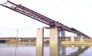
| a - Erection of continuous beam by incremental launching (продольная надвижка неразрезной балки) | b – Cast-in-place cantilevering (метод навесного уравновешенного бетонирования ) |
| 
|
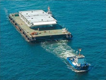
| c - Erection by floating into position (монтаж пролётного строения методом «на плаву») | d – Semi arch erection afloat (монтаж полуарок «на плаву») |
| 
|
| e – Superstructure erection afloat (монтаж пролетного строения «на плаву») | f - Steel arch is being lifted simultaneously with supporting (арка поднимается одновременно с сооружением опор) |
Figure 14.3 Various construction methods for superstructure erection
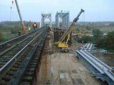
Incremental launching is a highly mechanised construction method. It is specifically suited for multi-span superstructures for very long gaps spanned by reinforced concrete continuous girders. These post-tensioned girders, cast on the bank behind one of the abutments, are from 15m to 30 m long. They are cast over a casting bed in a stationary formwork. Then cured and ready girders are pushed to the final position (fig. 14.2b). Each sufficiently hard newly cast segment is launched along the bridge axis in small increments with hydraulic jacks or by temporary sliding bearings. As the length of segments is long, and reinforced concrete has rather high density, builders use a launching nose attached to the cantilevering segment. The launching nose reduces the bending moment in the girder (fig. 14.2b; 14.3a).
This erection method has numerous advantages such as falsework elimination, reduced investment for special equipment, etc. However, it also has certain disadvantages, which limit its use: the concrete has to be prestressed in advance, and it needs time to reach a required density. Besides, the stationary casting bed cannot allow large changes in superstructure curvature.
Two cantilevering methods - cast-in-place cantilevering and balanced cantilever construction are suitable for framed suspended bridges, flyovers and trestles. Both fashions of cantilevering by building up new segments are very advantageous for bridging even inaccessible natural barriers.
Cast-in-place cantilevering or balanced concrete casting employs travelling shuttering for mounting the cast-in-situ segments that may achieve the length of 5.00 m (fig. 14.2c). The mobile frame, attached to the cantilever tip, supports the formwork with the newly cast segments. The mobile frame moves within the existing portion of the superstructure and constructs cantilever arms on either side of the supports. It stays in place until a newly cast segment gains sufficient strength, and then it moves forward. Normally, the duration of a casting cycle is about a week. In-situ concreting advances symmetrically, and finally cantilever arms connectd at midspan. The important advantage of this metod is that it leaves the waterway or valley beneath the bridge unobstructed during the superstructure construction.
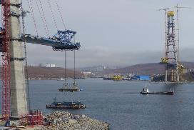
Structures of intermedium and long spans require cantilevering method, known as a balanced cantilever construction,when the erection of scaffolding is unfeasible due to site constraints. Cable-stayed bridges are ideally appropriate for construction by segments, prefabricated in casting yards. They are transported to the construction site where the workers mount them by gantry cranes or by mobile equipment, such as swivel cranes, fixed to the deck (fig. 14.3c).
As a rule, the superstructure construction starts from short stubs on top of piers, and proceeds symmetrically forming cantilever arms toward the midspan. The segments are stuck together with an epoxy adhesive or cement. This construction method leaves no possibility for later correction, and the workers fix segments exactly in the right position. Once cantilever arms are completed, they place the closure segment between them to construct a continuous superstructure.
Cantilever span may have either two arms proceeding from both sides of a pier or only one arm increasing from its abutment or on one side of a pier. When two cantilever arms are balanced in a scales-like fashion, cantilevering requires Balanced Cantilever Construction. The second type of cantilever system consisting only of one arm requires the Progressive Placement Method. In this case, the superstructure may need temporary towers.
A launching truss or launching girder is a different type of construction equipment forplacinginto positionthe set of precast segments or for castingsegments at opposite sides of the same pier. Thelaunching truss propels itself forward assembling the superstructure span-by-span. Thismethod is suitable for multi-span bridges when scaffolding is not feasible due to site constraints or difficult terrain conditions. The length and configuration of launching trusses provide a very high speed of construction.
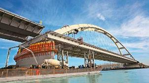
Arch bridges require rather complicated construction technology. The traditional method demands temporary piers and arch centering to reproduce the shape of the arch superstructure (fig. 14.4a). The precast reinforced concrete segments are placed on an arch centering.
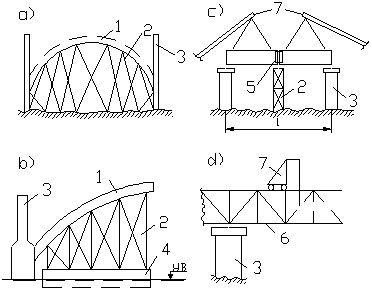
Figure 14.4 Superstructure Construction
a – Arch Erection by Arched Falsework (монтаж арки на подмостях); b - Arch Erection Afloat (монтаж арки на плаву); c –Long Beam Erection (монтаж длинных балок); d – Erection of Trussed Girder (монтаж сквозных ферм);
1 – Arch (арка); 2 - Arch Centering (кружала); 3 – Pier (опора); 4 – Pontoon (понтон); 5 – Block Junction (стык блоков); 6 – Trussed Girder (сквозная ферма); 7 – Crane (кран)
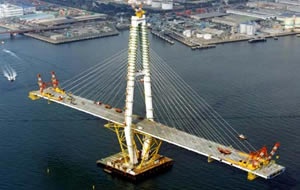
The cast-in-situ concrete arch is erected in a curved framework. The construction of arches above water is a much more advanced technique. The arches and semi-arches are assembled on the bank and transported to a barge, which carries these structures to the place (fig. 14.3d,e).
CONSTRUCTION OF SUSPENSION AND CABLE-STAYED BRIDGES
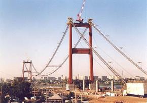
The suspension bridge is one of the oldest engineering forms, and currently it still is at the forefront of engineering innovation. Its span may grow to 3,000 m in near future. Constructing suspension bridges, the builders attach the roadway directly to their key elements - continuous steel cables made of thousands of high-strength steel wires spun together, either at the construction site or at industrial production locations. The fabrication of the cable includes the Air Spinning method (AS) (fig.15.1b) and the Pre-fabricated Parallel Wire Strand method (PPWS).
| 
|
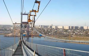
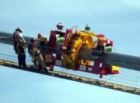
| a - Hoisting and Suspending of Catwalks | b – Air Spinning Method (AS) |
| 
|
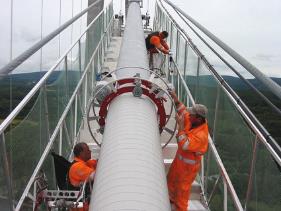
| c - Cables are compacted from individual strands | d - Protection of Main Cable (Cable Wrapping) |
Fig.15.1 AS construction methods for Suspension Bridges
The AS method is used for cable fabrication by spinning wheels that travel across the top of the towers to the opposite anchorage and back carrying the individual strands. The wheels are hanging on a continuous hauling rope, carried along a provisional path of the main cable by an overhead cableway between opposite anchorages. The hauling rope carries the wheels over temporary suspended walkways, called the catwalk. The catwalks follow the curve of each cable, and are made of a set of guide wires, wire grate and wood slats (fig.15.1c). Special winches mounted atop the towers hoist them into place (fig. 15.1a). Ironworkers, who must see to the process of cable forming, work on these walkways.
Each spinning cycle begins with placing a large spool of high-strength steel wire at the anchorage. The gauge of wire coated with corrosion inhibitors is typically 5 mm. First the wire handlers take the free end of this galvanized wire, make a loop, place it around a strand shoe and fix it to the anchorage. Then they make another wire loop, and place it around a grooved spinning wheel. The wire, held back by the anchorage, comes off the bottom of the wheel, laying on the catwalk. It is the dead wire. The wirethat comes fromthe spooland passesover the wheelis the live wire. The spinning wheel shuttles back and forth and spins the continuous cable strand by laying parallel wires. The wires are laid down on the tower top saddles equipped with rollers that allow free sliding of the main cables under live loads.
When the spinning wheel arrives at the anchorage, the crewmembers receive it and pull the wire loop from the wheel. They lay down the wire on the splay saddle, and connect it wire to the anchorage. The number of anchorage strand shoes is equal to the number of strands in the main cable, and all wires of each strand are attached to the same strand shoe. Then the workers send the wheel to the first anchorage to lay a fresh strand. They repeat the process until they have the necessary number of wires in a strand.
The ironworkers bundle the parallel wires into cable strands, and keep the strands together by taping or strapping them at appointed intervals. When the cluster of successive strands reaches the designed thickness, the crew removes the wraps from the individual cable strands and arranges compactor devices that squeeze the strands together to form the main cable (fig. 15.1c). The compactor compresses the strands into a closely packed cylinder throughout their length except at saddles and anchorages where the strands are separated.
The ironworkers also mount steel clamps called "cable bands". They aremade of paired semicylindrical steel castings, and mounted at predetermined locations at anchoring points where the vertical cables connect the bridge deck to the main cable with clamping bolts. Eachvertical or suspender cable has its preciselength and is looped over its cable band or connects a shackle-type fitting. The ironworkers coat the main and vertical cables with several layers of protective (fig.15.1d).
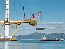
Finally, having attached the suspender cables to the main cables, the crew starts to build the superstructure. Travelling cantilever derricks move on the deck extending it in the opposite directions from the towers. Barges carry prefabricated deck segments to the site, and a moving crane, rolling atop the main cable, lifts them into place. The crewmembers connect deck segments to existing sections and secure them to the suspender cables.
The Pre-fabricated Parallel Wire Strand method uses full-length, prefabricated strands. First, the workers attach a pilot hauler rope to each anchorage to suspend the catwalk. The pilot hauler rope for the Akashi-Kaikyo Bridge was placed over the tower tops by helicopter. To fabricate each main cable, the builders transported each strand to the construction site, pulled each strand from one anchorage over the saddle of each tower, and then fastened that strand to the anchorage on the opposite shore of the Akashi Straits. They repeated that procedure 289 times, and then a cable-squeezing machine compressed the parallel wire strands into the main cable.
Barges transported the panels of the stiffening truss girder to the site, where traveler cranes lifted and transported them to the position, and the workers connected them to the suspenders. Lifting machines and equipment provided high-speed mounting due to 24 hours seamless operation. Finally, the main steel stiffening truss was attached to the main cable by suspender cable hangers.
As the cable-stayed bridge requires less steel cable and offers all the advantages of the suspension bridge, but at a lesser cost for spans up to 1,000 meters, at present it is a popular choice. The cable-stayed structure offers great stiffness with little building material, and looks very elegant. Usually it does not require anchorages because the cables connect the roadway with a single tower that alone bears the weight and resists compression forces. Depending on bridge design, stay cables can carry the bridge deck from one or both sides of the supporting tower transferring all bridge loads to the foundations. Free cantilevering method is suitable forconstructing cable-stayed bridges. This method is economical because the precast or cast-in-situ deck segments can be assembled by travelling shutter arrangement.
| 
|
| a - Balanced cantilever erection method | b - Cantilever erection of main girder |
| |
| c – Girder sections are delivered by barges |
Figure 15.2 Balanced cantilever erection method for construction of cable-stayed structures
The similar towers and hanging roadways of the cable-stayed bridge, at first glance, look like a variant of the suspension bridge, but their deck structures are unlike each other. The suspension deck, merely hanging from the suspenders, resists bending and torsion that can develop under live loads and aerodynamic forces. Construction of the suspension bridge deck cannot be started until the cables are entirely complete, but each span of a cable-stayed structure can be built out in stages from each tower (fig.15.2). The barges, which deliver the girder sections (fig. 15.2b,c), are exactly defined and positioned by GLONASS, a Russian global satellite navigation system.
BRIDGE MAINTENANCE
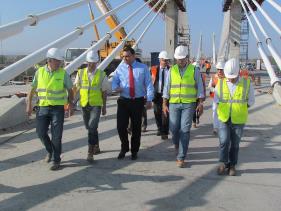
Bridge engineers plan their structures so that experts can easily inspect and maintain them. Once the bridge has been built, the State Acceptance Committee determines its availability status. Experts in the commission study all the documents, provide an on-site review and make visual inspection of the bridge components (fig.16.1). They examine them with geodetic devices to locate defects before they turn into a serious problem.
| 
|
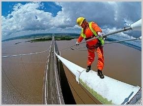
| a – Experts are making visual inspection | b- Bridge Inspector is assessing cable-stay condition |
Figure 16.1 Experts are inspecting a bridge
During acceptance inspection every structural element of the bridge is tested under static (fig. 16.2a) and dynamic loads (fig. 16.2b). Skilful specialists carefully examine welding and joints, which can change their initial position under an emergency load. If the structure meets the standard requirements and the acceptance documents are signed, the ownership of the bridge is transferred to the Railway and Motorway authorities or agents.
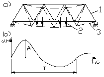
Figure 16.2 Diagram of Bridge Testing Under Static and Dynamic Loads
(схема проверки моста под постоянными и динамическими нагрузками):
a – Testing under Static Loads (проверка под статическими нагрузками);
b – Testing under Dynamic Loads (проверка под динамическими нагрузками);
1 – Superstructure (пролётное строение); 2 – Loads (нагрузки);
3 –Bridge after Deformation (мост после деформации);
4 – Vibration Amplitude (амплитуда колебаний); 5 – Period of Vibration (период колебаний)
Bridge maintenance presents many challenges even if a bridge is new. Steel bridges require a lot of maintenance in coastal regions because moisture and salts cause corrosion in the bridge components.
| 
|
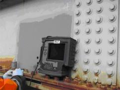
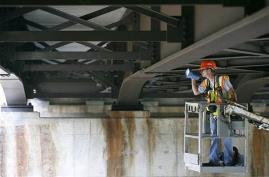
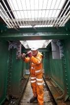
| a – Bridge Inspector is using Ultrasonic testing during the inspection of a bridge. | b - A regularly scheduled inspection of bridge components |
| 
|
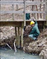
| c – Emergency state of a timber bridge | d - Routine inspection of bridge components and high-strength bolts |
Figure 16.3 Bridge Inspection
Coastal areas are also difficult environments for reinforced concrete bridges because moisture penetrates the concrete structure, deteriorates it and causes corrosion (fig.16.3a, b). Water can cause soil erosion making a bridge scour, undermine the footing and expose the piles. Substructure may be deteriorated at the water line, and suffer from cracking or impact damage caused by boats under the bridge, etc. Timber bridges can decay and be attacked by vermin (fig.16.3c). Bridges often need inspection after a flood event, onslaught of wind, fire, collision with boats or traffic accidents.
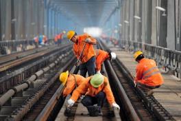
The Trans-Siberian Railway runs through permafrost areas, and bridges along this main trunk line require costly upkeep. As a lot of ice melts each summer, continual maintenance includes track leveling on railroad bridges (fig.16.4). In winter, extensive maintenance is also required to combat lifting up by frost when local displacements of 2.5 to 35 cm occur in roadbeds and bridges.
| 
|
| a - Workers examine the track on a railway bridge | b – After-inspection track repair on railway bridges |
Figure 16.4 Scheduled inspection and repair on railway bridges
Detailed visual bridge inspectionincludes not only checking the general condition of the structure but also looking for any problems with concrete or steel materials. The inspector must assess each bridge component and identify additional testing or repairs if needed. The information is reported to supervising engineers and maintenance crews. In case of emergency, a trained, professional engineer and a repair crew immediately fix the problem. An emergency inspectionis usually carried out after a flood event, an earthquake or a vehicle collision that damage bridge components.
Experts are responsible for safe bridge function, so they inspect and correct structures by running maintenance, preventive maintenance, scheduled bridge repairs, emergency repairs and overhaul. Preventive bridge maintenance is cost-effective because it provides the structure serviceability and allows avoiding expensive repairs. Construction inspectors and maintenance workers provide continuous bridge inspection throughout its service life. The rules and demands for scheduled and emergency maintenance must be observed according to the guidelines established by either “Building Specifications” or “National Bridge Inspection Standards”. Currently, there are accurate techniques for testing bridge structural integrity and safety. These techniques insure that bridges meet up to their designed specifications.
Usual bridge maintenance includes monitoring of cracks in deteriorated concrete, continual keeping the deck clean, periodical removing debris from bridge deck expansion joints, repairing apparent damage on the roadway surface, careful inspection of anchoring devices, protective painting, etc. Common maintenance concerns are welds, corroded rivets and bearings. They must be regularly flushed with high-pressure water jets to remove harmful precipitations and collection of sand or debris. The workers cleanse bridge deck, sidewalks, parapets and light stands using compressed air and mechanical devices.
Дата добавления: 2016-01-03; просмотров: 2159;