Read the text about the most astonishing British bridges and tell about them 3 страница
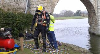
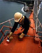
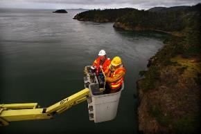
A civil engineer who assesses bridge condition is a Bridge Inspector or Structural Maintenance Engineer. He can perform tests to assess the aging of bridge components because he knows the behavior of bridge elements under different stress intensities. He assesses the structural damage caused by environmental influences or human actions. The experienced bridge inspector can work high up in the air (fig. 16.1b) or even underwater. Sometimes he has to put on underwater gear (16. 5a) to monitor the bridge components below the water surface or a scour around support columns.
| 
|
| a – Underwater Inspection of Bridge Components Condition | b – Painting of corroding steel bridge components |
| |
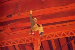
| c – Examining and replacing of corroding steel bridge components |
Figure 16.5 Bridge Inspectors assess the aging bridge components
To perform all necessary engineering supervision of long bridges, deal with bridge load capacity and column strength, do damage inspection and look for corrosion and fatigue cracking, bridge inspectors employ various assessment techniques such as Infrared Thermography, Ultrasonic or Standard Visual Inspection, etc. and use sophisticated monitoring devices and in-place sensors. To provide reliable, trouble-free operation many bridges are outfitted with monitoring devices based on acoustic emission and nondestructive evaluation (NDE) technologies. These techniques detect the acoustic reflections from growing cracks that can lead to disastrous failure of concrete (fig.16.3a).
A Bridge Maintenance Supervisor heads a crew of maintenance workers and equipment operators to inspecs short bridges and culverts. They monitor bridge safety; help the Bridge Inspector, remove and patch deteriorated concrete pavements before catastrophic failures can happen. They are responsible for removing ice, snow, slush, and storm debris. This work may result in short-term lane closures when traffic is not heavy, usually by night, but sometimes during daylight hours.
| 
|
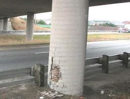
| a – Bridge maintenance personnel working in “skyboxes” | b - Bridge pier column with chipped concrete marked as the first category condition |
| 
|
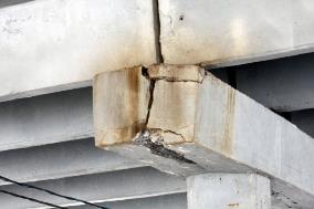
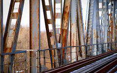
| с - Advanced deterioration with fatigue cracks marked as the second category condition | d - The third category of bridge condition calling for reconstruction |
Figure 16.6 General maintenance inspection is provided around the clock for assessing the categories of bridge condition
Maintenance personnel provides around the clock service locating and fixing small damage and defects: electricians inspect the navigation lights on the towers and main cables; examine light stands; bridge painters work in "skyboxes" touching up the protectivecoatings. For instance, 38 painters maintaining its well-known rust-red color and 17 ironworkers examining 1.2 million rivets that are corroding under never-ending fog perform daily maintenance procedures on the Golden Gate Bridge, which is crossed by more than 100,000 vehicles each day. Painting, monitoring rust expansion and replacing corroding steel components is the primary maintenance job (fig.16.5; 16.6). Having found wear and the exact anomalous zones in bridge components, a maintenance crew fills in the forms and keeps detailed and accurate records of bridge inspections and testing. They also keep a written record of wear-out failures, which need general overhaul.
The assessment categories of bridge condition are ranging from zero to the third category. The condition marked as zero category is the standard bridge condition when no problems are noted. The first category means that nearly all bridge elements are safe but the structure may have minor damage and failures such as cracking, spalling or scour. The workers repaire this damage during running maintenance (fig. 16.6b).
The second category means that the primary structural components are suffered from advanced deterioration with fatigue cracks in steel segments and shear cracks in concrete that may result in a pothole.The bridge or the component under suspect must be closely monitored, and correction action may require immediate repair or complete overhaul (fig. 16.6c). The third category means imminent failure that calls for reconstruction or complete replacement, and the bridge is considered to be out service (fig. 16.6d).
Maintenance cost may influence the bridge type selection. Concrete bridges usually require the least maintenance, which is crack sealing for preventing and reducing rebar corrosion. Timber structures are also an easy bridge type to repair. For instance, the workers replace decayed or broken planks with no difficulty and quickly fasten sound planks by metal fasteners. Access for inspection and maintenance is among the priorities of bridge engineering.
TUNNEL CLASSIFICATION
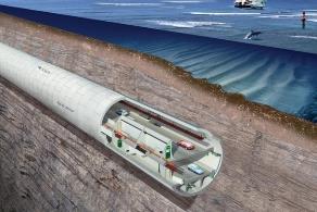
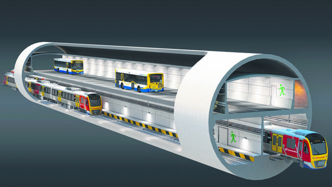
A tunnel is a long, completely enclosed on all sides man-made horizontal passage built under the ground with openings at each end. Tunnel entrance and exit are tunnel portals. The top half of the tunnel or the "roof" is the crown, and the bottom half is the invert. As tunnels must withstand tremendous pressure from all sides, thecontinuous arch is the ideal shape, especially for railway or motorway tunnels passing through a hill, under a building, road and river or under the sea (fig.17.1).
In general, tunnels must be at least twice as long as they are wide. Normally civic planners speak of a tunnel if it is at least as long as 0.16 km. A shorter structure is a chute. Relatively small-diameter tunnels serve as utility lines or pipelines.
Tunnels for transporting people by rail or by motor vehicles are rather complex structures accommodating two or more parallel passages for opposite-direction traffic, service machinery, and emergency exits.
| 
|
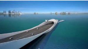
| a – Tunnel Portal | b – Underwater Tunnel |
| 
|
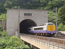
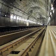
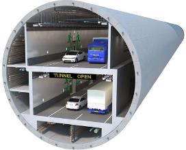
| c – Railway Tunnel | d – General Tunnel Structure |
Figure 17.1 Underground and Underwater Transport Tunnels
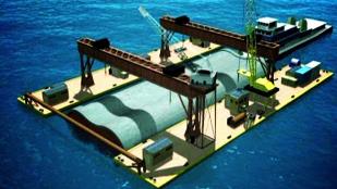
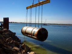
Underwater tunnels refer to immersed tunnels because they are commonly made of long, prefabricated tube sections, towed out to the construction site, and sunk in a dredged canal in the sea or riverbed (fig.17.2a). Sand or other backfill material cover immersed tunnels. These tunnels allow travel beneath bodies of water but they may obstruct or influence the moving of fish and create obstacles to water wildlife. Moreover, the immersion operations in waterways are rather difficult due to heavy currents, and in case of failure, this operation may result in serious cost escalation.
Many tunnels are technological masterpieces, for instance, the Seikan Tunnel that passes under the Tsugaru Strait. It is a 53-km long, 9.7-m diameter railway connection between the northern part of Japan’s main island of Honshu and the island of Hokkaido. Completed in 1988, it is the world’s longest person-carrying submarine tunnel. Its construction involved a 24-year struggle facing many challenges due to hard and soft rock excavation 100 m below the seabed where the sea is up to 140 m in depth.
| 
|
| a - Prefabricated tube sections for underwater (submerged) tunnels | b – A single tube section is ready for sinking |
| 
|
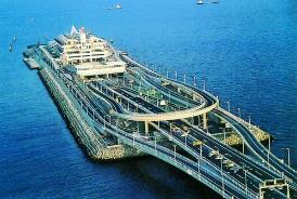
| c – An entrance to an underwater tunnel | d - An underwater tunnel entrance with opposing traffic |
Figure 17.2 Underwater Transport Tunnels
The earliest tunnelling belonged to prehistoric people who had to enlarge their caves, and their tunnels were hand-dug. Then several ancient civilizations in the Indian and Mediterranean regions developed tunneling methods. About 2160 BC the inhabitants of Babylonia constructed the 900-m long brick-lined pedestrian passage under the Euphrates River. Roman engineers built an extensive network of tunnels to carry water from mountain springs to their densely populated cities and to drain sewage away. These tunnels were part of the well-known aqueduct systems, which included sloping bridge-like structures supported by arches, and carrying water to the city of Rome.
The earliest canals, as man-made waterways used for travel, shipping or irrigation, inspired the construction of transportation tunnels through hills or mountains. By the 20th century, railways and roads had replaced the use of canals, and the notable tunnels appeared all over the world because the developing transport system needed them badly. For instance, the Holland Tunnel between New York City and New Jersey, completed in 1927, was one of the first roadway tunnels. It is one of the world’s greatest engineering projects. Our country also constructed the world famous Severomuiskiy Tunnel that is 15.3 km long. It was open to traffic in 2003 on the Baikal-Amur railway in the Russian republic of Buryatia.
Tunnels serve for transportation including metro, road vehicles and trains. They are also necessary for ore mining, for conducting water and sewage, for pumping stations, for underground hydroelectric-power plants and for canals. Subways, pedestrian passages, etc. also use tunnels.
Tunnels are the most complicated and costly engineering structures because underground work deals with various difficulties worsened by flammable gas, the weaknesses of the ground, the water inflow, etc. It took $21 billion to complete the Channel Tunnel (fig. 17.3) that appeared to be the most expensive construction project being 700 times more expensive than the construction costs of the Golden Gate Bridge.
All tunnels can be classified into one of the following criteria:
Criterion 1. (Tunnel function):
1.1 Transportation tunnels. (for travelling and carrying goods by any type of vehicle.)
1.2 Mining tunnels. (for extracting coal or other minerals.)
1.3 Utility tunnels. (for heat supply, gas, electricity, vision cable and phones in large cities.)
1.4 Waterpower tunnels (for hydroelectric stations) or hydraulic tunnels (to supply water for consumption and for sewage)
1.5 Secret tunnels for military purposes.
Transportation tunnels may be classified in the following way:
Criterion 1.1 (Mode of transport):
5.3.5 Railway tunnels.
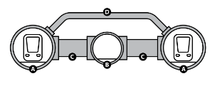
The Channel Tunnel, also called Euro tunnel, serves for freight and passenger traffic. It is 50 km long and runs underneath the English Channel between Folkestone, England, and Sangatte (near Calais), France. It consists of three tubes: two for rail traffic and a central one for services and security. Passengers can travel by ordinary rail coach or can stay within their own motor vehicles in special rail cars. The trip takes 35 minutes as trains travel at speeds as high as 160 km per hour.
1.1.2 Motorway tunnels.
1.1.3 Pedestrian tunnels.
1.1.4 Metro tunnels.
1.1.5 Navigation tunnels.
Criterion 2. (Tunnel location):
2.1 Flat ground tunnels.
2.2 Mountain tunnels. (for railways running through maintain ranges or watershed)
2.3 Underwater (submerged) tunnels or immersed tunnels.
The Mersey Tunnel in Great Britain links Liverpool (north) with Birkenhead (south). The construction began from both banks and the breakthrough took place beneath the riverbed in the middle of the river. Currently several tunnels beneath the Thames provide railway links (the twin Blackwall Tunnels – Southbound and Northbound), pedestrian walkways – the Greenwich Tunnel, and the first sub aqueous tunnel in the world, the Wapping-Rotherhithe Tunnel that was built in 1825, and refurbished in the late 1990s. This pedestrian horseshoe shaped cross-section tunnel is brick-lined. For many years, it was the largest soft-ground tunnel. Since 1913, the tunnel has been a part of the Tube.
Criterion 3. (Construction method):
3.1 Tunnels built by the cut-and-cover method.
3.2 Rock tunnels, built by the cutting method.
3.3 Shield driven tunnels.
Tunnelling under rivers was impossible until M. Brunel developed the protective shield in England. Jacks propel a shield forward and the workers put permanent lining segments in place under protection of the shield tail.
Criterion 4. (Tunnel laying depth):
4.1 Shallow-lying tunnels (up to 10 m deep).
4.2 Deep-laid tunnels (over 10 m deep).
Criterion 5. (Shape of the tunnel cross-section):
5.1 Rectangular section tunnels.
5.2 Circular section tunnels (the strongest shape).
5.3 Horseshoe section tunnels (flat bottom provides roadway).
| 
|
| a – A double deck motor tunnel | b - A double deck road-cum-rail tunnel |
Figure 17.3 Double Deck Tunnels
Some tunnels are double-decked (fig.17.3), for example, the Eastern Harbour Crossing in Hong Kong where the lanes for motor vehicles and rails (the MTR metro) occupy different decks. Drivers of private cars, public buses and special purpose vehicles use either the manual tollbooths or auto toll service to pay tolls for crossing the tunnel.
CONSTRUCTION METHODS OF TUNNELS
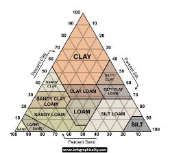
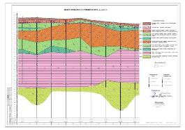
Being a passage excavated in rock or soil, tunnels are the ever-present challenge to civil engineers. Practically tunnels are excavated in various types of underground conditions, from soft ground and weak rocks to hard rock and underwater. Conventional desk studies do not provide sufficient details to assess the exact location of fault zones. Due to unforeseen geological constraints, any tunnel project starts with a comprehensive engineering-geological survey of rock conditions in term of hardness, extent of fracturing, etc. (fig.18.1).
| 
|
| a - Soft ground layers | b - Engineering-geological estimation |
Figure 18.1 View of different geological layers
As a single tunnel may pass through more than one type of rock, it is essential to reduce the risk of facing gas- and water bearing strata in the early stages of tunnelling. Engineers conduct a thorough geologic analysis for selecting the proper tunnelling technologies, and for choosing the type of support to obtain safe tunnel systems.
Tunnel engineers often use the term “driving” for expressing the general idea of tunnel building though construction methods may be very diverse. For instance, tunnelling through loose or soft ground such as sand, sandy loam or clay is very different from tunnelling through hard rock such as granite, basalt, quartzite, or soft rock, such as shale, chalk or sandstone. The builders evaluate the site geology by driving a probe-type tunnel ahead of the tunnel face. It helps to select the construction method.
Tunnelling history started with manual labor using hand digging tools, rapid heating and cooling. Then it advanced to the cut-and-cover method, drill-and-blast method using explosives, and shield tunneling devised by Marc Brunel and James Greathead who constructed two tunnels under the Thames River. More than a hundred years later, the American engineer James Robbins invented the TBM (tunnel boring machine) which is suitable for longer, circular tunnels. It could move forward grinding rock and soil by digging or cutting heads mounted on its rotating front face. The arrangement of their cutting heads matches the site geology and makes TBMs widely used and customized for any tunnel type. Truck-mounted drilling jumbos equipped with several high-speed pneumatic drills with replaceable cutting bits can also work in hard rock, controlled by a single operator. Muck is loaded into tracked cart driven by electric locomotives, which run along narrow-gauge tracks. The gauge in tunnels ranges from 600 to 750 or 900 mm.
| 
|
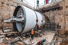
| a – Tunnel excavating started from a vertical shaft. | b - A launch chamber (камера запуска) |
| 
|
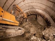
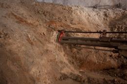
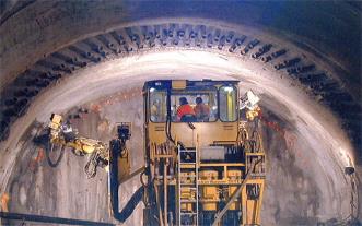
| с – Excavating the calotte ground by a drilling jumbo (открывание калотты буровой кареткой) | d – Drilling holes for placing charges of explosives (бурение шпуров для закладки зарядов) |
Figure 18.2 Stages of tunnel excavation
Generally, tunnel builders use two basic techniques. Passing through strong ground and building smaller tunnels, they use the full-face method excavating the entire tunnel diameter at the same time. Digging a smaller tunnel known as a heading, they normally use the top-heading-and-bench methodusing the individual excavation phases for heading, bench and invert. The heading tunnel helps in assessing the rock stability before moving forward.
As most tunnels are excavated through rock that comprises breaks or pockets of fractured rock, engineers must strengthen tunnel walls and crowns with sprayed concrete, bolts, or a permanent concrete lining.
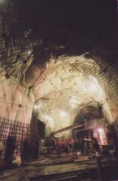
Tunnel excavating can start with a vertical opening called a shaft (fig. 18.2a). Unlike the actual tunnel, shafts are shorter, and serve for analyzing the bedrock or providing headings for excavating the tunnels. In this shaft, large launch chambers are excavated for assembling TBMs (fig. 18.2b). Alternatively driving may start from a horizontal tunnel or an entry drift. Tunnelling underwater or through mountains normally started from the two opposite ends of the passage.
Hard rock tunneling through mountains involves subdivision of the tunnel cross section into several drifts, and driving them sequentially (fig. 18.3). This excavation method comprises the following phases:
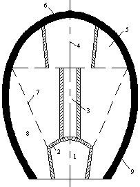
Figure 18.3 Hard-Rock Tunnelling (горный способ проходки тоннеля)
1 – Lower Drift (нижняя штольня); 2 – Temporary Support (временная крепь);
3 – Footway (ходок); 4 – Top Heading (верхняя штольня); 5 – Calotte (калотта);
6 – Lining (обделка); 7 – Middle Drift (средняя штросса);
8 – Side Wall Drift (боковая штросса); 9 – Lining (обделка)
Driving starts from the lower drift (1) with temporary support (2) and vertical or inclined footways (3), dug towards the top heading (4). The next step is to penetrate into the top tunnel sides known as the calotte (fig.18.2c), i.e. driving the top drifts intended for crown lining (5). If the tunnel crown is fractured, it requires supporting immediately after excavation (6). Then the middle drift called the stros (7) is cut, and finally, the sidewall drifts called side strosses (8) are excavated. To prevent water entering in the driven areas, drift miners accommodate a watertight lining made of bolted segments with sealing gaskets. To stabilize soil or fill voids behind the tunnel lining, they may inject grout. The muck is transported out, and the tunnel is given its final lining to support the adjacent ground.
Hard rock tunneling almost always involves the traditional “drill and blast” method, which requires the following phases:
Blasting crew drills a predetermined pattern of blast holes in the rock (fig.18.2d), and places carefully planned charges of explosives into the drilled holes so that they detonate in the right sequence without damaging the adjacent rock. Then the workers are evacuated and the explosives are detonated.
The next phase is removing noxious blast fumes and dust by exhaust ventilation. The workers often use water to control dust after blasting and during drilling. As safety is always the first consideration for blasting crews, the workers enter the tunnel for finding the unexploded charges, and for removing debris dislodged by the blast. Tunnel muck is transported to the entrance where dumper trucks remove it. Then the drift miners smooth the surface of the blasted section by pneumatic drills and hand tools, and repeat the process for advancing the tunnel further through the rock.
Shallow lying tunnels are usually built by the cut-and-cover method within the excavated trench with the necessary ground support, and covering it with backfill. The tunnel may be built of precast archesor in situ concrete and other materials. Once the trench is carefully backfilled, the road workers restore the roadway on top of the tunnel. This technique comprises two basic forms: the bottom-up or caisson wall method and top-down or diaphragm wall method.
A major challenge for tunnelling in soft ground and weak rock is the high groundwater level. When driving is below the water table, it requires very close control. To ensure the face stability. drift miners use either compressed air or TBMs. Excessive groundwater inflow can be suppressed by a temporary lining followed by a final permanent lining made by a liquid concrete called shotcrete that is sprayed on tunnel surfaces.Currently concrete is reinforced by either steel or fiber. When a layer of shotcrete about 7 cm thick is sprayed onto the tunnel walls, it is reinforced by one or two layers of wire mesh placed to it. Alternatively, the shotcrete might be strengthened by adding reinforcing fibers.
As weak rock is prone to collapse and can clog digging equipment, water-saturated ground, boggy ground and quick sand require some stabilization methods such as freezing soft soil or injecting grout into fractured rock. Small pipes are embedded in the ground at intervals, and a refrigerant such as water-and-salt brine or liquid nitrogen, circulating through these pipes, freeze the soil.
| 
|
| a - the New Austrian Tunnelling Method (NATM) with wire mesh, rock bolts (Новый Австрийский метод с использованием металлической сетки и анкерных болтов) | b - the New Austrian Tunnelling Method (NATM) with the double layer of tubes installation (Новый Австрийский метод с использованием двойного слоя труб) |
Figure 18.4 the New Austrian Tunnelling Method (NATM)
Tunnelling techniques are largely dependent on rock compressive strength, water and gas pockets, the number of cleavages, etc. Tunnel builders monitor the deformation in weak rocks and provide efficient tunnel support made of shotcrete, wire mesh, rock bolts and lattice girder (fig.18.4). The builders registered this method, based on the inherent rock potential, as the New Austrian Tunnelling Method (NATM). It provides high-performance tunnelling and high levels of safety for underground teams.
Maintaining ground stability during tunnel construction and ensuring structural integrity of the tunnel lining are crucial factors in tunnelling technologies. However, of no less importance is achieving the proper alignment of the excavation path. The global positioning system provides the proper tunnel alignment tunnel by the sensors receiving accurate location data via satellite signals (fig.18.5).Engineers also use laser guidance systems to provide quality control of tunnel alignment by projecting and detecting a laser beam within the tunnel.
To complete the construction of the tunnel, workers install ducts for carrying the cables to provide the safety systems and lightning. Summarizing the opportunities and challenges inherent to building a tunnel, one can take the conclusion that tunnel technologies involve a combination of different methods.
SHIELD TUNNELLING
Tunneling through soft rock requires special consideration as the tunnel’s path may encounter various sorts of hazardous ground conditions such as pockets of methane gas, stretches of water bearing sands, swelling clay, quick sand, silt, mud, gravel, areas of high water inflow, etc. Poor geological formations including sections with severe tectonic pressures as well as stretches of high-pressure water are highly dangerous for driving. Cave-ins are also an ever-present threat while driving in weak rocks due to short stand-up time during which the ground at the point of excavation stands safely by itself. Tunnelling with drill-and-blast method, even with the most up-to-date explosives, is usually unsuitable in soft rock because blasting in shale or limestone is rather difficult to control. These challenges call for clear engineering ideas that can minimize all risks. A special piece of tunneling equipment known as a shield protects workers and provides support (fig.19.1).
The early models of a shield, implemented between 1820 and 1865 by M. Brunel and J. Greathead, were of rectangular or circular shape. Shields had horizontal and vertical bulkheads that made compartments for workers who could dig the entire tunnel face. A Greathead-style shield was followed by the tunnel boring machine (TBM) constructed by J. Robbins.
| 
|
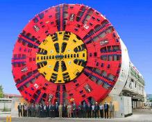
| a - Shields are powerful sealed steel cylinders for cutting and lining | b - Shields are equipped with mechanisms for ventilation and power supply. |
Figure 19.1 Tunnel Shield Boring Machine (TBM)
Shield technology is very efficient compared to other types of tunneling because modern TBMs do not just cut and protect, they remove excavated material and provide exploratory drilling, ground control and support. They are powerful sealed steel cylinders equipped with mechanisms not only for cutting, gripping and lining, but also for ventilation and power supply.
| 
|
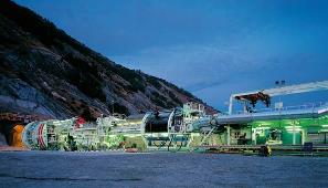
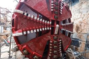
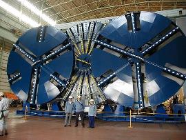
| a - Rotating cutting wheel covered with a combination of milling cutters, disk cutters and steel rotating disks | b - Japanese triple tunnel boring machine |
Figure 19.2 Components of the Rotating Cutting Wheel
TBMs carve a perfectly round opening and support the excavated earth until a permanent lining made out of prefabricated concrete segments is installed. Shield tunneling allows full-face driving without dividing the heading into portions, and the progress rate may be 15-30 m per day or even 300 m/week, as it was during the construction of the Channel Tunnel. No other driving methods can achieve that result.
Present-day TBMs or “moles” are enormous, multimillion-dollar complex systems that match various kinds of the site geology due to the types of cutting devices and their arrangement on the face of the shield (fig. 19.2a).
Дата добавления: 2016-01-03; просмотров: 1684;