Read the text about the most astonishing British bridges and tell about them 1 страница
In 1779, Abraham Darby wrote a new page in the world’s bridge engineering history by building the first cast-iron bridge to span the Severn at Coalbrookdale in Great Britain. Designed by Thomas Pritchard, the bridge, constructed of cast-iron pieces, imitated stone construction with nearly semicircular 30-metre arch span (fig. 8.1a; 9.4a). Cast-iron plates covered each of its five thin cast-iron arch ribs. Despite the arch is slightly humped, the bridge is still used today but not for vehicles. It is now a British national monument.
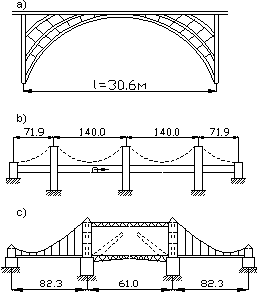
Figure 9.4 Bridges of Great Britain
a – the earliest cast iron bridge across the Severn River; b – the Britannia Bridge;
c – the Tower Bridge
The upcoming of railways during the 19th century resulted in new bridge forms strong enough to resist the dynamic loads of trains. The most significant of these early railway bridges was the Britannia Bridge by Robert Stephenson across the Menai Strait. He supported a pair of completely enclosed iron tubes of rectangular section by a pier in the centre of span. He was the first to employ the hollow box girder, which gave the deck the extra stiffness of a truss. The workers delievered the iron tubes afloat, and then a capstan and hydraulic power lifted them. The lengths of spans are 140 m and each abutment span is 71 m long (fig. 9.4b). The bridge builders completed the structure in 1850.
There were towers for chains on the bridge. The towers were originally to carry the wrought iron boxes through which the trains ran. Now they are useless because there are no cables on the bridge. In 1960’s the structure was severely damaged by fire, and during the repairs the tubes disappiered completely. Steel arches support modern concrete deck. At present, the bridge carries railway and motor traffic (fig. 9.6a).
SUSPENSION AND CABLE-STAYED BRIDGES
Early people developed one of the oldest engineering forms, known as suspension bridges. They mounted the roadway directly on cables made of vines (fig. 10.1a). Suspension bridges are light, aesthetic, graceful and easily constructed with materials, which builders can readily transport. Besides, there is no danger of failure during erection because the principal carrying member - the cable – easily endures overstressing. Using cables with relatively small dead weight, it provides an economical solution to the problem of long spans over navigable streams or rivers (fig.10.1b). Since the cables are in tension, they are the most highly efficient load-carrying component. Besides the economic considerations, the suspension bridge has many other points of merit.

| 
|
| a - The Earliest Suspension Bridges | b - The Golden Gate Bridge, the USA |
Figure 10.1 Suspension Bridges
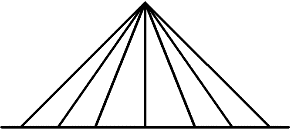
The structure with the supporting cables or stays connected directly to the bridge deck without any suspenders is a cable-stayed bridge. The basic systems of cable arrangements are radial or converging, harp, fan and star cable systems. When the builders anchor all cables to a common point at the tower top, the cable system is radial (fig. 10.2a).
| 
|
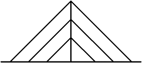
| a – radial pattern cable system with all cables anchored to a common point at the tower top | b - harp pattern cable system with parallel cable-stays |
| 
|
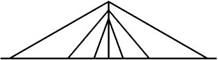
| c – fan pattern cable system with non-parallel cable-stays | d – star pattern cable system with cables descended at different heights and convergedat common points of the deck |
Figure 10.2 Diagram of Cable Arrangement in Cable-stayed Structures (геометрические схемы вантовых мостов)
If the cable arrangement looks like harp strings since the cables run in parallel and have equal distances along the tower height and between the neighboring points where they are attached to the superstructure, the bridge has the harp cable system (fig. 10.2b). The radial and the harp systems may be combined resulting in the fan-type cable system. In this case, the cables descend from the top of the tower at equal distances as in the harp cable system, and are attached to the superstructure at larger distances (fig. 10.2c). This arrangement is widely used, as it is, structurally, the most effective. The star system looks rather extraordinary as the cables descend from both sides of the tower at different heights. Then they convergeat common points, and are attached to the deck at the opposite sides of the tower (fig. 10.2d).
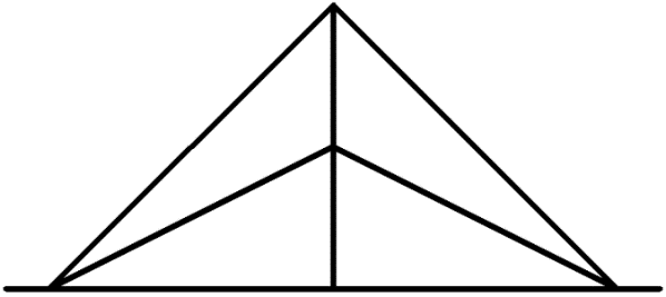
The suspension and cable-stayed bridges are often confused as, at first glance, they may look similar, but actually, they are quite different. However, both structures have very much in common - stiffening girders or trusses, anchor supports and cable hangers, their main bearing members are different in shape.
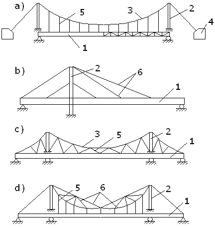
Figure 10.3 Diagram of Suspension and Cable-Stayed Bridges (висячий и вантовый мост)
a – Suspension Bridge (висячий мост); b - Cable-Stayed Bridges (вантовый мост);
c – High Stiffening Suspension Bridge (висячий мост повышенной жёсткости);
d - Cable-Stayed Truss (вантовая ферма)
1 – Stiffening girder (truss) (балка [ферма] жёсткости); 2 – Tower (пилон);
3 – Flexible Cable (гибкий кабель); 4 – Anchor (анкерная опора);
5 – Suspender (подвеска); 6 – Cable Stay (ванта)
The usual form of suspension structures consist of flexible cables passing over two towers. The cables are anchored to a steady foundation. The roadway is suspended from the cable by hangers. The main carrying element of a cable-stayed system is a straight cable (fig. 10.3; 10.4).
The two following criteria determine the difference between these two bridge types:
1. A suspension structure has curved steel cables or chains (fig.10.3a; 10.4a).
2. A cable-stayed structure has straight cables (fig.10.3b; 10.4b).
| 
|
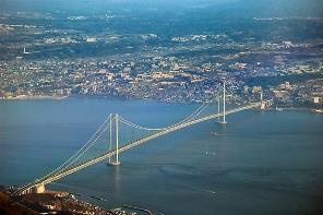
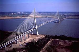
| a – Suspension Bridge (The Akashi Kaikyo Bridge, Kobe, Japan) | b – Cable-stayed Bridge (the Normandy Bridge) |
Figure 10.4 Suspended Bridge Structures
Modern bridge engineering uses the suspension span model at the large scale. The Akashi Kaikyo Bridge (fig.10.4a), now the world’s longest suspension bridge, crosses the strait with a main span of 1,991 m and side spans of 960 m. Two 297 m high towers, made of two hollow steel shafts connected by X-bracings, are the tallest bridge towers in the world. The cables are made of high-strength steel developed for the project by Japanese engineers. In 1995, an earthquake had its epicenter almost directly beneath the nearly completed Akashi Kaikyo structure; the bridge survived undamaged, though one tower shifted and lengthened the main span by almost one metre.
There are some types of suspension bridges without anchors. Their main cables are directly attached to the girder at both ends thus forming self-anchoring suspension structures.
The basic advantages of suspension and cable-stayed structures over other bridge types are:
1. The possibility to span very long distances from 500 m up to 1,990 m.
2. Construction by simple materials such as wood and common wire rope.
3. Less material may be required even at long spans. It results in reducing of construction cost.
4. High efficiency of these structures is due to the weight of the span per square metre, which is considerably less in comparison with other bridge systems.
5. The installation of the initial temporary cables allows a waterway to remain open for navigation while the bridge is under construction.
6. Suspension bridges may withstand earthquake movements much better than other bridge types.
7. Suspension and cable-stayed bridges often have merits that are more aesthetic than heavier and more rigid bridges.
The disadvantages of suspension and cable-stayed structures compared with other bridge types are:
1. Low vertical stiffness, i.e. the structure strongly exhibits high deflections under live load especially due to railway traffic because of the low deck stiffness.
2. Low horizontal stiffness, i.e. the structure exhibits considerable deck vibrating and displacement in a horizontal plane by wind force.
3. High sensitivity to dynamic and aerodynamic forces.
4. Some access below a suspension structure may be required for lifting the initial cables and deck segments, though this disadvantage can often be avoided in case of cable-stayed bridges.
To ensure high performance of suspension and cable-stayed bridges and prevent the deck from moving excessively under loading, the following factors are paid attention to:
1. Only high-strength steel wires with a rated resistance of 10,000 MPa are used.
2. Stay cables should be loaded only in tension because working in compression may result in suspension bridge collapse.
3. No weakening in suspension bridge cable is allowed.
4. Cable hangers and stay cables support the stiffening girder at many sites.
5. The stiffening girder transmits its dead weight to the cable and the towers. Such girder’s behaviour is due to the special construction technique.
The stiffening girders distribute the load in the span and prevent distortion of the deck. To make the stiffening girder lighter the planers use the force regulation in stay cables. This results in the most acceptable distribution of force. Each suspension structure is unique and designed with due consideration for both function and aesthetics. Currently bridge engineers construct striking suspension structures that are more efficient and less bulky owing to new building materials.
Modern technologies have heavily instrumented suspension bridges with measuring devices for determining vehicular weight or environmental characteristics including temperature difference, wind speed, etc. A global positioning system (GPS) is able to monitor the movements of suspension bridges with a high accuracy.
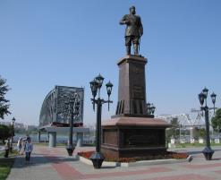
BRIDGES OF NOVOSIBIRSK
Novosibirsk is one of the largest cities in Russia. Its development in the 21st century relies on its ideal geographical location at the crossing of basic transportation routes – railways, airlines, waterways and motorways. It sprang from the intersection of these routes and became an important transport centre for local, domestic and foreign transportation of goods from Siberia, the Far East, the Kuzbass region, the Altai Region, Central Asia, Kazakhstan, Mongolia, China, Japan and the rest of the world. The role of the railway network is of paramount importance as it gave rise to the business activities of many regions. The Trans-Siberian Railway is the longest in Russia, stretching from Moscow 9,198 km east to Vladivostok. It has great importance in the economy of our country, and crossing many unique bridges, it carries 9.5 million tons of cargo each year.
| | 
|
| a – the Rail Bridge across the Ob River (1897) | b – the Original Truss of the Rail Bridge (1897) in the “City Dawn” Park |
Figure 11.1 The Rail Bridge that gave the birth to the city of Novosibirsk
At the end of the 19th century, the builders of the Trans-Siberian Railway had to bridge the mighty rivers of Siberia. The surveying party headed up by N. Garin-Mikhailovsky chose the most suitable place for crossing the Ob River. Professor N. Belelyubsky conducted the planning of the first huge railway bridge across that water obstacle. The builders laid the first stone to the bridge foundation on 20 July in 1893, and the residents of Novosibirsk consider this date to be the birthday of their city. The railway crossing was open to traffic in 1897 (fig. 11.1a; 11.3a; 11.4). During the years of the bridge construction, the village of Krivoshchekovo on the left riverbank gave rise to a settlement that, later, developed into the largest city in Siberia, in the very centre of Russia.
| 
|
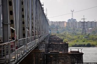
| a – the Railway Bridge by N. Beleljubsky after Reconstruction in 1981 | |
| 
|
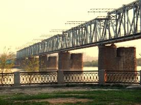
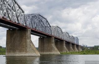
| b - the Komsomolsky Railway Bridge (1935) | c- the Oktyabrsky Bridge and the Metro Bridge |
| |
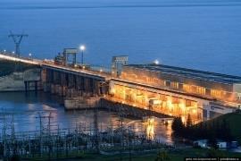
| d – the dam | e – the Bugrinsky Bridge (design model) |
Figure 11.2 Bridges in the City of Novosibirsk
Nearly a century the bridge provided a safe passage for heavy trains, but the bearing capacity of its elements and the state of the riveted joints could not resist modern live loads. The deterioration of bearings called for reconstruction, which began in 1981.
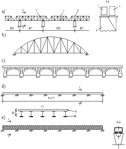
Figure 11.3 the Novosibirsk Bridges
a - The Earliest Railway Bridge (1896); b – The Railway Bridge (1935);
c – The Oktyabrsky Bridge (1956); d – The Dimitrovsky Bridge (1978);
e - The Metro Bridge (1985)
1. Beam-cantilever Trusses (балочно-консольные фермы);
2. Suspended Trusses (подвесные фермы); 3. Bearings (опорные части);
4. Piers (опоры 1896); 5. Superstructure (пролётное строение 1896);
6. Superstructure (пролётное строение 1981); 7. Slender Arch (Гибкая арка);
8. Braced Girder (жёсткая балка); 9. Reinforced Concrete Slab (железобетонная плита);
10. Steel Girder (металлическая балка);
11. Composite Superstructure (сталежелезобетонное пролётное строение)
The renewed railway bridge is a multi-span superstructure with a cantilever-beam metal truss (fig. 11.2 a; 11.3a; 11.4). The suspended span is 87 m long and rests on the cantilevers of the adjacent trusses. The main advantage of a cantilever-beam truss is that each pier has one bearing. It reduces pier proportions at the bridge facade. The headroom provides 118 m of navigable waterway. New metal trusses rest on piers with concrete encasement. Concrete also encases the starlings. The planners redesigned the old spans, and Belelyubsky’s bridge entered their next cycle of its service life (fig. 11.2a; 11.4).
The next railway bridge across the Ob River appeared in 1935. Young enthusiastic people built it within a short period, and called the structure the Komsomolsky Bridge. It has a metal riveted truss with a top flange of polygonal shape (fig. 11.2 b; 11.3b; 11.4).
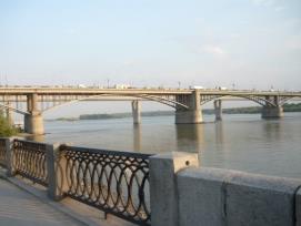
Insecurity in transport communication held back the economy growth in the rapidly developing city. A floating bridge in summer and an ice passage in winter were the only communication links between the right and left riverbanks until 1956. Further industrial growth was encouraged due to the Oktyabrsky Bridge (fig. 11.2c; 11.3c; 11.4), which solved the traffic problem.
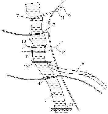
Figure 11.4 Plan of Novosibirsk Bridges
1 – the Ob River; 2 – the Inya River; 3 – the Railway Bridge 1896; 4 – the Railway Bridge 1935; 5 – the Dam of Water Power Station; 6 – the Oktyabsky Bridge 1956; 7 – the Dimitrovsky Bridge; 8 – the Metro Bridge; 9 – Novosibirsk-Glavny Railway Station; 10 – Karl Marx Avenue; 11 – Dimitrov Avenue; 12 – the Metro Line; 13 – the Bugrinsky Bridge
The first town bridge in Novosibirsk is one of the finest bridgeworks in our country. The bridge spans combining strong metal girders and low angle arches gracefully complement the magnificent city view. The bridge spandrel looks especially attractive. The deck is made of reinforced concrete slabs allowing much easier asphalt spreading on a roadway. The piers resisting the weight of the arches might look rather ponderous but due to the nice granite encasement, they decorate the bridge.
Novosibirsk is a rapidly developing city because it stretches out at the most important overland transport cross routes. The Main Federal Motorway carries heavy traffic through our city that causes great inconvenience in the streets. The problem of traffic congestion, noise and air pollution made the authorities build a bypass road for freight transportation at the northern border of the city. Again, the Ob River became a natural obstacle to the new road, and a reinforced concrete bridge was badly in need. The Prime Minister of The Russian Federation opened the bypass to traffic on October 22 in 2010 (fig. 11.4).
Senior government and RZD COMPANY officials, as well as the Transport Minister, other high-ranking persons, and the General Manager of the West-Siberian Railway Branch accompanied Mr. Putin. Having examined the new bridge, they came to the Siberian State University of Railway Engineering and discussed the plans for transportation development. The Prime Minister signed “The Strategy of Transport Development up to 2030”. This document provides many solutions for our transport problems.
BRIDGE OR TUNNEL?
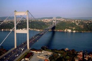
Vast bodies of water, all over the world, represent natural obstacles to communication. People have been striving to overcome water obstacles by bridging the gap between continents, islands, etc. The English Channel separating Great Britain and Europe, the Straits of Gibraltar between Spain and Africa, the Bosporus between Europe and Asia, the Bering Straits connecting the Eurasian and American continents are the busiest shipping routes. The opposite shores of these straits are dotted with villages, towns and cities that need safe and reliable transportation by overland or underground railway and motorway networks.
Each time, considering the problem of individual water-crossing facilities, civil engineers, who plan, design, construct and maintain roads, bridges, tunnels, and similar structures, face many challenges. They always have the choice between bridge and tunnel crossings (fig. 12.1, 12.2).
| | 
|
| a - The Amakusa Islands, connected by bridges to mainland Kyushu, Japan | b - The Fatih Sultan Bridge (Bosporus II) in Instambul |
Figure 12.1 Bridges connecting separated areas
Each sort of structure offers its own advantages and has some imperfections. One should bear in mind the influence of strong sea currents, high water depth, large-capacity vessels with large overall dimensions (free shipping needs the headroom of 65 m high), and difficult geological structure of the seabed. For instance, seabed silt is rather soft for pier foundations. Tunnels circumvent difficulties with tides, weather and shipping during construction. Besides, destroyed by a terrorist attack or during battles, bridges can block the shipping channel for weeks or even months before the wreckage could be removed.
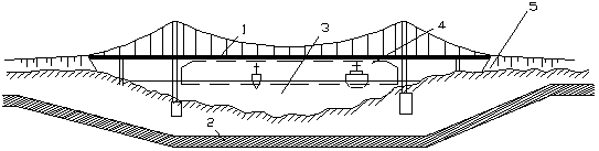
Figure 12.2 Bridge Crossing, Tunnel Crossing
1 – Bridge; 2 – Tunnel; 3 – Large Body of Water; 4– Bridge Clear Span;
5 – Embankment
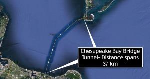
Some water crossings are a combination of bridges and tunnels. A bridge-tunnel is a facility where a bridge passes into an underwater tunnel. Such unique water-crossings include the Denmark to Sweden link, the Chesapeake Bay Bridge-Tunnel in the United States (fig.12.3), the Tokyo Bay Aqualine, etc. The Tokyo Bay Aqualine is a marine crossing consisting of a tunnel, a bridge and two artificially made islands. Its total length is more than 15 km.
| 
|
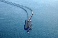
| a - The Chesapeake Bay Bridge-Tunnel Complex | b – One of the artificial islands with the tunnel portal |
Figure 12.3 Chaesapeake Bay Bridge-Tunnel
The Chesapeake Bay Bridge-Tunnel is a complex including two low-level trestles that are 19 km each; four artificially made islands that provide portals for entering the tunnels; two deeply sunk long tunnels beneath the shipping channels; two high-clearance bridges that are more than 3 km long; causeways and 9 km of approach roads. The length of each tunnel is 1.5 km long. This complex, opened to traffic in 1964, is 37 km long.
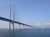
The next unique structure is the Oresund Bridge by Georg Rotne, built across a narrow channel between Sweden and the Danish island of Zealand (fig.12.4). Queen Margrethe II and King Carl XVI Gustaf opened the link to traffic on July 1, 2000. The structure is the longest combined road and rail bridge in Europe, and the longest border crossing bridge in the world. The international European route E20 runs across the bridge and through the tunnel connecting Copenhagen and the Swedish city of Malmo. The Oresund Bridge is a striking spectacle as its 204m high pylons with their harp-shaped stay cables are visible from the Swedish and the Danish sides.
The total bridge length is 7,845 metres, its width is equal to 23.5 metres, and its weight is 82,000 metric tons. It has one of the longest cable-stayed main spans in the world equal to 490 metres and a navigational clearance of 57 metres. This fixed link is on two levels and carries two rail tracks beneath four motorway lanes. The railway runs along the lower deck while the motorway runs along the upper deck. People travel over the bridge by cars, buses and trains that run every 20 minutes, and once an hour during the night. The daily volume of traffic across the bridge is 17,000 road vehicles but the toll for driving the fixed link is high.
| 
|
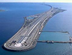
| a - The Oresund Bridge | b - Entering to the Oresund Tunnel on the artificial island |
Figure 12.4 The Oresund Link between Denmark and Sweden
The bridge ends in the middle of the Oresund Strait (the English name of the strait is the Sound) and passes into an immersed tunnel on an artificially built unpopulated island that is more than four km long and a few hundred metres wide (fig. 12.4b). The tunnel connects this island and the nearest populated part of Denmark. It is 4,050 m long and has two 270-metre gate-tunnels. The tunnel provides a clear passage for boat traffic. Since the structure is actually a bridge and a tunnel, technically it is more correctly to call it the Oresund Link or Oresund Connection. The total cost of its construction, including motorway and railway connections on land is expected to be paid back by 2035.
Examples of water-crossing tunnels built instead of bridges include the Holland Tunnel and Lincoln Tunnel under the Hudson River in New York City, and the Elizabeth River tunnels in the USA.
The advantages of a bridge crossing are the following: low construction costs in comparison with tunneling, though sometimes the reverse may be true; low maintenance costs in comparison with tunnels, which require costly water discharging, ventilation, illumination, etc. Lane capacity in tunnels is also lower when compared to bridges. In addition, underwater tunnels have vehicle restrictions for hazardous cargo, and require 24-hour staffing known as patrol officers for incident management and operation under life-threatening emergency.
The advantages of the tunnel are also obvious. Being deep beneath the water’s surface, tunnels provide unobstructed shipping that is very important for intensive navigation. Besides, the weather does not influence the vehicles running through the tunnel. The design aspect of the tunnel is more attractive because there is no need to accommodate high approach embankments.
The final decision for choosing between the two structures often falls in favour of bridges, for instance, the outstanding bridge across the Bosporus constructed in 1974, and the bridge crossings connecting several Japanese islands in 1985. Nevertheless, the choice fell on a tunnel underneath the English Channel in 1994. It provides a high-speed rail-link reducing the travel time between Great Britain and France to three-and-a-half hours. The cost of this tunnel is enormous.
Currently, tunnels are widely used for rapid communication in states surrounded by water because they offer a much safer way than bridges or ferries traveling through stormy sea. Japan built the Seikan Tunnel because a typhoon sank five ferryboats crossing the Tsugaru Strait in 1954. Having considered a variety of solutions the Japanese government proposed a railway tunnel because any bridge that could withstand severe weather conditions would be too difficult to construct and maintain.
The problem “a bridge or a tunnel” is under discussion for planning future structures across the Straits of Gibraltar and the Bering Straits. The choice falls on a bridge crossing in Europe, and on a tunnel for Alaska due to harsh northern conditions. The idea of constructing an intercontinental bridge or tunnel between Alaska and Siberia is actually not very new as Tsar Nicholas II dreamed of the railway and tunnel that could close the gap between Siberia and North America. Currently this bold idea needs governmental study by both the RF and the USA. A 65-mile-long tunnel, built in three sections, could pass underneath the Big Diomede and Little Diomede islands in the Bering Strait. It could be twice the length of the Channel Tunnel and might cost approximately $10-12 billion. It would be the world’s longest tunnel that could improve a railway network of the Northern Hemisphere and provide efficient transportation corridor for goods and passengers as well as transmission lines and communication by fiber optic cables.
CONSTRUCTION OF SUPPORTS AND FOUNDATIONS
Bridge engineers design and calculate their structures so that the bridge can safely withstand the dead weight; the live load produced by vehicles moving across the bridge; changes in temperature, precipitation, and winds; and, finally, environmental factors including sudden gusts of wind and earthquakes known as the dynamic load.
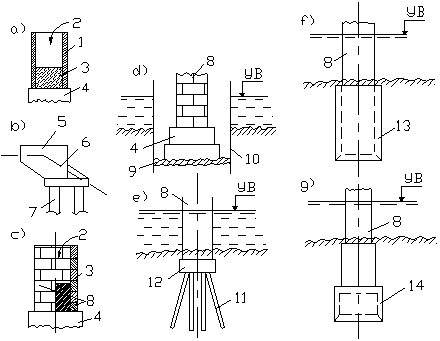
Figure 13.1 Diagram of Piers and Foundations (cхема опор и фундаментов)
a – Cast-in-situ Pier (монолитная опора); b – Precast Pier (сборная опора);
c – Composite Pier (сборно-монолитная опора); d – Foundation on Natural Bed (фундамент на естественном основании); e – Piled Foundation (свайный фундамент);
f – Coffer (опускной колодец); g - Caisson Foundation (кессонный фундамент)
1 – Casing (опалубка); 2 – Concrete Feeding (подача бетона);
3 – Poured Concrete (уложенный бетон); 4 – Footing;
5 – Abutment Blocks (блоки устоя); 6 - Footing; 7 – Pile (свая);
8 – Composite Pier (сборно-монолитная опора);
9 – Concrete Grouting Layer (тампонажный слой бетона);
10 – Sheet Piling (шпунтовое ограждение); 11 – Pile Foundation (свайный фундамент);
12 – Grillage (ростверк); 13 – Coffer (опускной колодец); 14 – Caisson (кессон)
In most cases, bridge piers are made of concrete and/or reinforced concrete. Steel piers may support flyovers and trestle bridges but not frequently.
Дата добавления: 2016-01-03; просмотров: 1663;