Consult this list of English-Russian equivalents while studying the text
| 1. Construction arrangement | конструктивные схемы |
| 2. Head resistance of the rock | лобовое сопротивление грунта |
| 3. Pre-feasibility study | технико-экономическое обоснование |
| 4. Preliminary study | предварительное исследование |
| 5. Specifications | технические условия, требования |
| 6. Trial trip | пробная поездка |
STRUCTURES IN THE UNDERGROUND
The metro is one of the most efficient mode of public transport. It is a very complicated system including track ways between stations. The metro track differs from conventional railway track.
| 
|
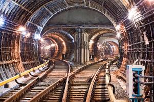
| a - General Arrangement of the Metro Interstation Tunnel (Общий вид перегонного тоннеля метрополитена) | b - Crossover Chambers with scissors crossings (Камеры съездов) |
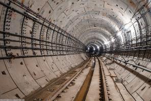
Figure 22.1 General Arrangements of Metro Tunnels
The rails in the metro rest on concrete sleepers to keep the air free from dust. Were the track embedded in slag, gravel, sand, earth or even broken stone, called the ballast, the trains would be followed by dust clouds. The metro sleepers are shorter (0.9 m.) than those for the heavy rail track (2.7 m), and are separated by a drainage gutter (fig. 22.1a; 22.2). The contact rail, laid alongside the track throughout the line, carries a high voltage of 825 volts. It is attached to the brackets and transmits direct current to the train electromotor through the current collector (fig. 22.1; 22.2).
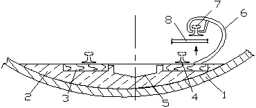
Figure 22.2 Layout of the Underground Track (схема пути метрополитена)
1 - Tunnel Lining (обделка); 2 – Concrete Base (бетонное основание);
3 – Semisleeper (полушпалок); 4 – Rail (рельс);
5 – Drainage Gutter (водоотводной лоток); 6 – Bracket (кронштейн);
7 – Contact Rail (контактный рельс);
8 - Train Current Collector – (токосъёмщик поезда)
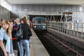
The main part of any underground railway system is an interstation tunnel (fig. 22.1a). It may be a one-way tunnel with single track or a tunnel with double tracks. The New York Subway has four-track sections including a regular express service. The total length of the New York Subway is 337 km with 468 stations that are operated around the clock and used by 21 one-way lines and three shuttle services. Three-track sections are used for express service during rush hours.
The lining in the tunnels has a circular shape (fig.22.1). As a rule, it is made of reinforced concrete segments or cast iron liners in separate units. The trains divert from one track to another using crossovers (fig. 22.1b; 22.3).

Figure 22.3 Diagram of Crossovers and Stub-end Tracks (схема съездов и тупиков)
1 – Crossover (съезд); 2 – Stub-end Track (тупик); 3 – Train-set (поезд)
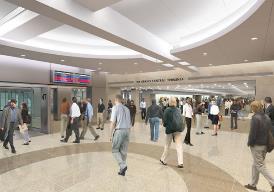
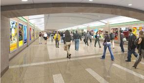
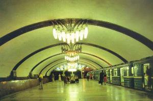
The metro carries yearly millions of passengers, and the stations are collection points for them. A metro station is usually a surface or an elevated railway station with ticket offices and automatic fare collection gates (AFC) or turnstiles (fig. 22.4c). The logo of each metro company marks the entrance of the station at street level. Station planning must provide a safe environment for passengers and meet the functional and aesthetic requirements. Attractively designed metro stations represent a continuation of the aboveground architecture. They are fully air-conditioned with required temperature and humidity though the stations are deep below street level. Usually passengers do not notice whether they are moving above or below ground because the structural layout itself creates the atmosphere of “a city within a city”, and the underpasses are densely packed with retail outlets.
| 
|
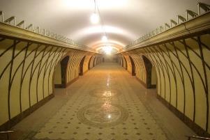
| a - entrance/exit | b – concourse (вестибюль) |
| 
|
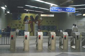
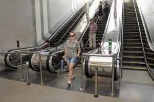
| c - entrance turnstile (входные турникеты) | d – three-band escalator |
Figure 22.4 A typical underground station
A typical underground station may have up to several ground level entrances and exits. They should allow for straight and short passageways that connect entrances to the fare paid zone, which is behind the line of turnstiles. Station access points must be equipped with one or more wide gate for wheelchair users and passengers with baby carriages. The width of the underpasses should range between 2 and 6 m, the height cannot be less than 2.5 m. The routes must be unobstructed and information including route maps is clearly visible throughout the station. The signs must display messages in English and in the native language.
Sanitary engineering, air ventilation chambers, lifts and ancillary rooms further facilitate the metro station. Disabled and passengers with heavy luggage and trolleys can use lifts.
The number as well as sizing of the platforms, escalators and subways, which are station elements, is dependent on the number of people using the station. To determine the optimum capacity of an underground station it is necessary to consider not only the number of passengers passing by continuously, but also the maximum number of passengers the station can deal with effectively. The regular number index of any station is measured by the number of passengers for a station and is equal to 20-30% of total train capacity. If stations are located near terminals, theatres, etc. the quantity index must be equal to 50%. The stations located next to large sports stadiums or concert arenas have the quantity index that is equal to 100% of overall train capacity because occasional events generate a powerful passenger flow over a relatively short period.
It has become common to provide escalators for upward and downward movement, and to allow passengers to change levels within the station. Escalators connect the underground platforms with concourses, staff offices and E&M plant rooms with electrical and mechanical equipment. An escalator system involves an inclined tunnel for three moving stairs, a power-driven station to move the stairs, fig. 22.5) and a tensioning station for a tensioning device.
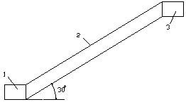
Figure 22.5 Escalator Facility (эскалаторный комплекс)
1 – Tensioning Station (натяжная камера); 2 – Escalator Tunnel (эскалаторный тоннель);
3 – Power-driven Station (приводная станция)
The diameter of the inclined tunnel is 8.1 m. Sometimes there are normal stairs between the two moving lanes, used in case the escalator breaks down. Stairs and escalator widths must be adequate for emergency evacuation. Today’s escalators provide ever increasing levels of reliability, comfort, roughened handrails and non-slip treads (fig.22.4d). The driving machinery uses the planetary gear arrangement with lower energy consumption because one direct drive machine powers both steps and handrails. The escalator safety enhances if the movement of step band and handrail is fully synchronized.
The performance of modern escalator systems is due to reliable technology and “intelligent” electronic monitoring and control. If malfunctions occur, automatic control units help to find them quickly. Stop switches provide safe access to all escalator machine spaces to enable the authorized personnel to keep the equipment in service. As escalators may go out of service, each metro system has its own program of ongoing maintenance and continuous monitoring.
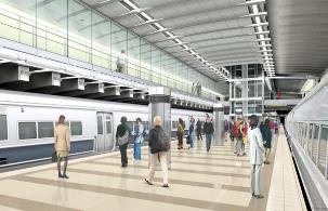
Platforms are very important parts of the station as passengers gather, enter the trains and change routes (fig. 22.6 a,b; 22.7) there.
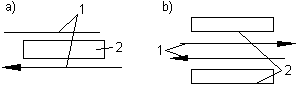
Figure 22.6 Diagram of the Underground Stations (схема станций метро)
1 – Track (путь); 2 – Platform (платформа)
Two factors regulate the overall configuration of stations. The first is the train length that determines a clear platform length. The second factor is the choice between side or island platforms (fig. 22.6; 22.7).
| 
|
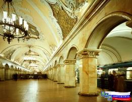
| a - Single Span Station (односводчатая станция) | b - Deep pillared-trispan Station |
| 
|
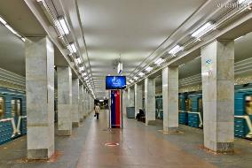
| c – Station with simple flat-slab ceiling | d- Station of side type |
| 
|
| e - Single Span Station of island type | d - Station of island type with simple flat-slab ceiling |
Figure 22.7 Types of Metro Stations
When double-bored tunnels are proposed, island platforms are preferred. A single row of columns in the centre of the platform or on both platform sides is a normal structural solution. A column-free platform also offers advantages, including an enhanced feeling of spaciousness. Architecture and interior design should satisfy passenger needs. Seating should provide passengers with comfortable waiting for trains but should not form any obstruction. Floor surfaces should be firm, easy to clean and made out of non-slip materials. Artificial lightning enhances the interior of the station. Platform edges must have strips of high contrasting colour (hazard tape) to warn passengers and prevent access to the tracks.
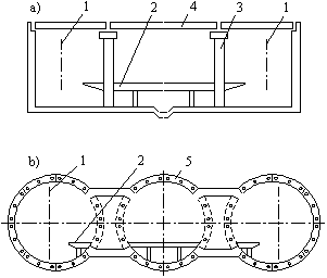
Figure 22.8 Diagram of Structures of the Underground Stations
(схема конструкций станций метрополитена)
a – Shallow-laid Station (станция мелкого заложения);
b – Deep-laid Station (станция глубокого заложения);
1 – Track (путь); 2 – Platform (платформа); 3 – Pillar (колонна, стойка);
4 – Ceiling Slab (плита перекрытия); 5 – Tunnel Lining (обделка)
Some platforms are equipped with automatic platform screen doors, which allow a full load of passengers on and off the cars within 90 seconds. These doors allow people to enter the cars only when the train stops in accurate alignment with the barrier doors. Platform screen doors differ from platform edge doors (PEDs). The former are total and full height barriers between the station floor and ceiling, the latter do not reach the ceiling. Besides these two, there are automatic platform gates called half-height platform screen doors. They are chest-height sliding doors at the edge of passenger platforms creating a safe waiting environment and preventing people from accidental falling or deliberate jumping off the platform waiting area onto tracks where they can be electrocuted or run over. Many stations on the Jubilee Line and the Canary Wharf Station in London, are equipped with glass protective barriers, and contain bright coloured banding to make them more visible.
Pillared-trispan structures are constructed for deep stations (fig. 22.7b). The central span is used for a passenger platform and the side spans are used for track ways. Span ceiling stations have pillars, which serve as the principle-bearing element. The result is a perfect harmony between attractiveness for the eye and technology. As a rule, the floors of shallow-laying stations are made of flat panels (fig. 22.7d). All station platforms, escalators, corridors and tunnels are under closed circuit television surveillance.
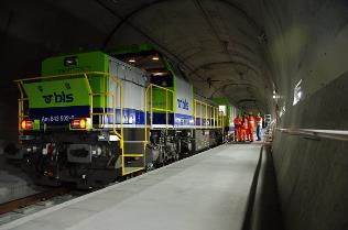
TUNNEL MAINTENANCE
Railway, metro and motorway tunnels need a lot of effort to keep them safe, clean and reliable. To ensure their faultless maintenance is a daily challenge to tunnel managers, supervisors, foremen and other specialists. To meet the highest reliability and safety standards the key personnel must keep tunnels in excellent technological condition, and provide minimal traffic disruption.
The Eurotunnel, being the world’s longest undersea railway tunnel, pays much attention to its maintenance because it is handling the world’s highest density of traffic. The rails wear out rather quickly as they carry a load of around 120 million tonnes each year. It poses extreme demands on the track inspection, and during the years of operations, the Channel Tunnel’s specialists have already replaced the rails twice. Their approach to maintenance includes the “Maintenance Production Plan” that covers a detailed description of each maintenance operation for improving tunnel performance in terms of reliability.
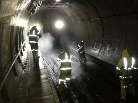
Tunnel maintenance covers upgrading the track sections; after-inspection repairing of signaling equipment and signs; examining of a “third rail” electric system; improving reduced light intensity; cleaning of air treatment filters, removing rubbish, dust and other contaminants; etc (fig. 23.1b). Both coarse and fine dust particles, deposited in tunnels especially during the braking of the trains or rail grinding, cause malfunction in telecommunication and signaling equipment, etc. An efficient filtering system cleans the air because the passengers can inhale the dust, and if it exceeds legal limits, it can pose a health risk. These problems are far worse in metro tunnels because train frequency is much higher and air moves through the tunnels into stations. Metro tunnels are cleaned more often than railway tunnels because the confined tunnel space aggravates high rates of dust generation.
| 
|
| a – Inspection carriage | b – Maintenance crew removing rubbish, dust and other contaminants |
| 
|
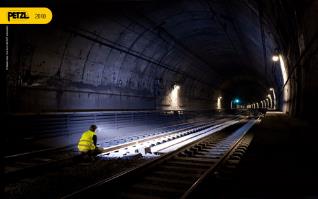
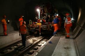
| c - Examining the track, rail fastenings and joints | d – Reconstruction crew examines the faults and conducts necessary repairs |
Figure 23.1 Routine tunnel maintenance
Day-to-day tunnel maintenance is much more expensive compared to the upkeep of bridgeworks and culverts. Maintenance supervisors and tunnel trackwalkers work side by side with a maintenance crew belonging to a specific track section. Due considerations should be given to the track, rail fastenings and joints (fig. 23.1d). They are carefully examined for faults, and necessary repairs are conducted daily (fig. 23.1e). The workers supported two parallel rails with the gauge of 1,520 mm at the same level. It prevents accidents and eliminates any possibility of derailment.
The next maintenance concern is providing steady tunnel height and width clearances. The workers test them by a trolley, equipped with a frame matching the tunnel’s dimensions. In case a tunnel is built in a seismically active area, its lining is influenced by the shift of the Earth’s crust and other displacement processes within the massif. The aim of the permanent close inspection is to examine the shifts in lining elements and the incipient cracks in concrete and iron cast segments. The maintenance crews use special screeds attached to the lining surface to watch the displacement changes.
Water discharging is one of the complicated problems for tunnel maintenance especially in icy conditions. When the water in gutters, laid on both sides of the railway track, freezes, the ice blocks the trains. The gutter dimensions depend on the amount of water entering the tunnel. They call for extra maintenance cost under low temperatures, because they need heating or require special encasement to keep them warm.
Water infiltration can cause tunnel degradation and safety risks due to settlement of eroded and weakened tunnel structures. Infiltrated water dissolves road salts carried by vehicles into tunnels. This concentrated solution increases deterioration of tunnel structures. Poor concrete cover cannot protect reinforcement steel that corrodes and causes concrete delaminating and spalls. Weakened and corroded tunnel structures and equipment including fans, lights, etc. pose danger to vehicles traveling through the tunnel during a seismic event.
Tunnel maintenance also deals with ventilation and lightning. Ventilation is one of the most complicated problems. Road tunnels face this problem because of its confined space. Air contamination resulting from toxic auto emissions calls for various types of ventilation facilities. The simplest ventilation method proposes constructing the opposite tunnel portals at different levels to provide natural ventilation. There is another type of natural ventilation in short tunnels with large cross-sectional areas. They take advantage of the prevailing winds influencing air movement. Moreover, moving traffic creates the “piston” effect by pushing the air through the tunnel. Bi-directional traffic reduces the effect of natural ventilation, and engineers can add a centre shaft to the tunnel ventilation system. Fresh air can enter the tunnel and smoke-filled or gas-polluted air can exit through this shaft.
Long or heavily traveled tunnels have large amounts of air with high levels of dust, exhaust gases and other contaminants. To replace the polluted air within the tunnel and to make its circulation more frequent, some tunnels are equipped with a separate plenum or ductwork for supply-air and exhaust-air systems. The ductwork is located either above a suspended ceiling or below a floor slab within a circular cross-section tunnel. The supply or exhaust ductwork also may be along both sides of the tunnel. Mechanical supply-air fans may be accommodated at both ends of the plenum, and push fresh air from a pollution-free source, usually from the portal, towards the centre of the tunnel. Some ventilation systems use reversible fans that can flow the air in opposite directions.
Rectangular-shaped tunnels with no extra space for a separate plenum above the ceiling or below the roadway employ longitudinal ventilation that is similar to natural one. There are additionally mounted mechanical fans of longitudinal ventilation inside the tunnel. The engineers may also install fans either in the portal buildings or in the centre shaft. Short circular tunnels also use the longitudinal system because the amount of air that needs replacement is not large.
Many tunnels are equipped with ventilation plants including the vent stack and machinery rooms with fans, dust collectors, mufflers and ventilation control devices. The air is supplied alongside the whole length of the road reducing the volume of toxic agents within the tunnel environment. Diluted vehicle emissions are absorbed near the tunnel exit and discharged after the dust is removed from them. Then clean air is discharged from the tunnel, and detecting devices control the leakage of exhaust gas into the outside environment.
Tunnel lightning is very important for safe maintenance and traffic. The magnitude of light level must provide such illumination that inspectors can clearly see the track elements without using additional light sources and flashlights. Tunnel illumination should also provide sufficient light for correct adaption of drivers from the bright portal conditions to the darker tunnel illumination. For this purpose, there are brighter lights, installed at a certain length at the tunnel entrances.
Usually fluorescent lights, installed in long tunnels along their entire length, provide the appropriate amount of light for both nighttime and daytime conditions. Moreover, the walls and ceiling in long tunnels are faced with a highly reflective surface msde of tile or metal panels. Short tunnels may not require daytime illumination due to the natural light entering the tunnel through the portals on both ends.
The Tunnel Manager and Tunnel Supervisor share the ultimate responsibility for ensuring tunnel maintenance. These individuals must ensure accurate records of performed repairs and of incidents that happen with tunnel equipment. They are also responsible for training of tunnel personnel and for inviting outside specialists when they are required to perform work on tunnel equipment.
СOLLAPSE OF BRIDGES AND TUNNELS
Throughout the world, millions of people travel each day with perfect confidence in transport reliability. Bridges and tunnels play an important role within the transport network, but they are at risk everywhere. Risks are serious because most old bridges and tunnels do not meet modern traffic demands, which have significantly changed since the old structures came into service.
| 
|
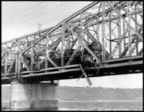
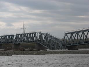
| a - Bridge damage caused by train derailment | b - Bridge collapse caused by the pier washout |
| 
|
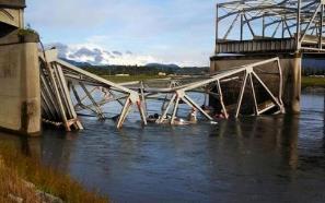
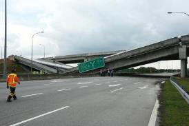
| c – The collapce of the Road Bridge in the city of Mount-Vernon (the State of Washington) on May 24,2013 | d – The collapse of the flyover and main pipe running along it in Cyberjaya (Malaysia) on February 28, 2013. |
Figure 24.1 Bridge failures
Much attention should be given to bridge and tunnel accidents to avoid train derailments and other tragedies (fig.24.1a). Engineers must provide assessment of bridges and identify structures with poor structural conditions or deficiencies. They must thoroughly review train accident data and adopt stringent safety assurance protocols to prevent deterioration or degradation of railway bridges for reducing the risk of structural failures and casualties.
The main reasons causing the failure and destruction of Railway and Motorway Engineering Structures refer to the following four groups: natural disasters (earthquakes, hurricanes, floods and avalanches); various blunders in engineering and technical decisions; negligence and ignorance in construction and maintenance recommendations; and, last but not least, traffic accidents.
More than 100,000 earthquakes occur each year, and no place on the Earth is safe from tectonic pressures. Sudden, abrupt and violent shifts in the Earth’s crust result in vertical and horizontal displacements, which can put the piers into a slanted position and crush or throw off the spans. However, it is worth noting that during quakes bridges and tunnels have not been damaged as much as other civil engineering structures. An earthquake crushed about 85% of dwellings in Tokyo on September 1, 1923 but only 337 out of 1,028 bridges went out of service. Moreover, the Great Tashkent Earthquake in 1966 affected no Railway and Motorway Engineering Structures.
The impact of ice can also be dangerous for bridges. In 1938 ice accumulation on the Niagara River cut the abutment of the arch span, and the 256-m span collapsed. One more reason for bridge collapse is the scour of pier foundations. The current in the Russian River Uvod increased due to its channel constriction in 1881. It produced a 5-m hole in the soft riverbed. The pier foundations lost stability, and the bridge collapsed (fig.24.1c).
The next challenge for bridges is their construction and maintenance under harsh freezing conditions. The superficial knowledge of metal characteristics and the behaviour of metal structural elements resulted in sudden and unexpected collapse of the Hasselt Road Bridge in Belgium in 1938. When the air temperature dropped abruptly below freezing, some of the metal arch elements broke without any additional loads. The collapse occurred due to the high carbon content in steel elements that caused metal increased brittleness under cold conditions.
Each division of Railway Company should maintain an accurate inventory of its bridges by conducting detailed comprehensive bridge inspections at least once per year. Competent engineers must determine the capacity and condition of each bridge. They must accurately record the inspection information in detail.
Tunnels also play an important role within the transport infrastructure. If an accident occurs in a tunnel, it will have a destructive effect not only inside the tunnel, but it will also influence the surface environment because vehicles may carry hazardous freight. Safety Standards guarantee a high level of safety, but tunnels face problems with large water inflow, which can cause tunnel collapse.
The Kirov-Vyborg Line (Red Line) in the St Petersburg Metro passes through the centre of the city. Its running tunnels and stations are at a depth of 60-70 m under several rivers and at the proximity to the Gulf of Finland. Due to poor geologic conditions, the builders faced a water leakage, and more than 10,000 cubic meters of water mixed with soil flooded into the tunnel. The builders managed to complete the tunnel, and the line was open to traffic, but in 1995, the 500-meter tunnel section at this very station-to-station block was flooded again and collapsed. Water and sand were falling from the tunnel roof and walls but fortunately no one was hurt. Water pressure against the dam located nearby the tunnel caused the repeated washout at the same tunnel section. Additional load resulted into cracks spreading in the tunnel lining. When the tunnel was crumbling, technical and emergency crews were among the first on the scene. To relieve pressure on the tunnel walls and to avoid the further collapse and damages on the surface, the opened dams flooded the tunnel. That segment of the line was out of sevice during nearly ten years. Normal service started in 2004 after having built a set of tunnels along a new alignment. The Slurry Tunnel Boring Machine performed the excavation work of this section and could assure the face stability towards a water pressure in the most difficult water bearing soils.
Owing to the enclosed space of a tunnel, accidents, particularly those involving fires and collisions, can have dramatic consequences leading to the traffic disruption, and destroy a region’s economy. The main dangers are highly toxic accumulations of gas and smoke. The tunnel fire accidents with the highest number of fatalities occurred in tunnels with narrow profiles and with a single-track line (fig. 24.2a,b).
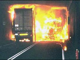
| 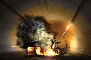
|
| a – A fire accident in a vehiclular tunnel | b – A truck and car collision in a vehiclular tunnel |
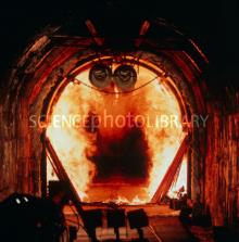
| 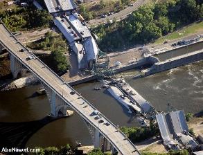
|
| c – A fire accident in a rail tunnel | d - The collapse of the Interstate 35W Bridge over the Mississippi River in the USA |
Figure 24.2 Collapses of Tunnels and Bridges
For instance, the fire in the Baku metro in 1995 killed most of the passengers because the concentration of heat and smoke became unbearable. The narrow cross-sectional tunnel area (28m²) contributed significantly to the severity of the accident and did not allow evacuation. In the Euro tunnel fire in 1996, the train stopped next to an emergency exit but the concentration of smoke and fire gases, following the train was very high and prevented people from using the exit. The passengers could escape into the parallel tunnel due to a bubble of fresh air, injected into the tunnel through the emergency exit. Railway convention throughout the world demands that, if a train is caught on fire in a tunnel, people are evacuated at the first confirmation of a fire. The installation of fire suppression stations in each running tunnel is also a strict demand to stop costly fire events.
Security is the watchword in the modern world, which makes the transport system authorities more watchful because of dramatic terrorist attacks. A suicide bomb attacks destroy metro trains resulting in fatalities and casualties. Therefore, railway and motorway operators must increase their preparedness, detect potential threats and take the correct and immediate action. Public transport staff must be well trained to prevent dangerous situations. Installed video-surveillance systems, along with recording observe tunnels, turnout tracks at the endings of the lines, etc. Video images constantly analyse and detect abnormal situations. The alert systems, based on the video records, work automatically. Security-related measures can help to prevent and handle incidents, and passengers can avoid panic and confusion. The designers of Railway and Motorway Engineering Structures must plan facilities for reducing the tragedies because the daily security is Job Number One.
UP-TO-DATE BRIDGE AND TUNNEL ENGINEERING IN RUSSIA
At the turn of the third millennium Russia has displayed impressive achievements in bridge and tunnel engineering due to state-of-art construction methods developed by Russian research teams and applied by engineers. Their accumulated experience in design and building methods has resulted into engineering structures with enhanced quality. One of the largest Russian manufacturing corporations TechnoNICOL produces special materials for bridge and tunnel structures for protection against water attack and for heat insulation. Another producing company ITS (Engineering Technological Service) from St Petersburg supplies welding equipment and flux covered wire. Most trusted Russian suppliers of bridge components offer their bearings, seismic protection and monitoring systems, expansion joints, etc. They offer long-term experience and cost effective, secure on site application.
During the celebratory event, when the Big Obukhov Bridge (fig. 5.2h) in St Petersburg was being commissioned, President V. Putin said: “This bridge has proved that the best traditions of our engineering school are alive, they are steadily developing in accordance with the highest standards and using the state-of-art technologies”. The cable-stayed bridge, built in 2004, is the first passage across the Neva River for the “river-sea” class vessels of up to 30 m high. It is the third longest in Russia after the Surgut and Vladivostok Bridges. The bridge carries four expressway lanes, a tramline and a railway line. The Big Obukhov Bridge collected 7,220 votes in the “The most beautiful bridge in Russia” Contest.
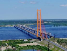
The road bridge across the Ob River in Surgut (fig.25.1a) was open to traffic on September 16, 2000. The bridge has become the major transport project in Russia at the end of the XXth century that met the world standards using domestic technologies, building materials, equipment and highly qualified personnel. The Surgut Bridge is one of the longest bridge crossings in Siberia with total length including the access roads of 15 km. The bridge established a record among single tower cable-stayed structures with the central span length of 408 m. It is the longest in the world acoording to the Guinness Book of Records. Its design and construction allowed development of new methods of theoretical calculation, experimental investigation, fabrication methods, and construction of complicated structures in severe climatic conditions. Having built this bridge, Russian engineers proved their ability to meet modern challenges of bridge engineering.
| 
|
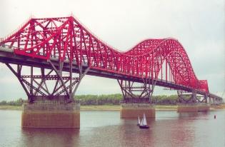
| a - The road bridge across the Ob River in Surgut | b - The road bridge “Red Dragon” across the Irtysh River in the city of Khanty-Mansyisk |
Figure 25.1. Modern bridges across Siberian Rivers
A cable-stayed structure span the shipping channel, and a continuous beam span the rest of the river in both directions. The architectural merits of the Surgut Bridge are truly captivating with its towers looking like two orange arrows rising up to 149 m in height. Their cross bracings look like a lace net. Practically invisible stay cables connect the tower with the stiffening girder under different angles (from 20° to 70°). The Surgut Bridge also competed for the top position among the most attractive bridges in Russia.
The road bridge “Red Dragon” across the Irtysh River in the city of Khanty-Mansyisk (fig.25.1b) was open in 2004. The river with heavy water craft traffic is 1,100 m wide under the bridge, and features different water levels. The total bridge length is nearly 1,316 m. This unique structure is the key element of the federal road from Perm to Tomsk. The combined system “arch+truss+beam” consists of the central through arch span followed by a continuous steel beam and a trussed girder with top and bottom polygonal chords. The through arch truss has flexible tie-bars, and the adjacent spans are through trusses with wind bracings. The locals call the bridge by the endearing nickname of “A sleeping baby dinosaur”. The main five-span structure is 231 m long, which is the fourth longest in Russia. It claims to be the most attractive bridge in Russia. According to the Internet contest held on the website of the Federal Road Agency of the Ministry of Transport in 2012, it collected 27,500 votes.
| 
|
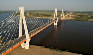
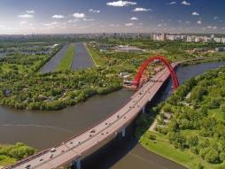
| a – the Murom Bridge across the Oka River | b - The Zhivopysny Bridge in Silvery Woodland across the Moskva River |
Figure 25.2 Modern bridges in European areas of the Russian Federation
The Murom Bridge (fig. 25.2a), which is the fourth cable structure built in Russia, was put into operation on October 1, 2009 by Prime Minister V. Putin who landed his helicopter just on the bridge deck. Speaking to the builders, Putin called their result as an impressive feat. The bridge was an acute need because it was the only way to link the south Russian regions with the city of Nizhny Novgorod. The total length of the bridge crossing is 1.5 km, and it is 15 m wide. The traffic capacity of this bypass reaches 20,000 vehicles per day and in this way, it diverts heavy traffic flows from the centre of Murom to P125.
The cable-stayed structure rests on three concrete towers of 86 m high. The towers are separated from each other by the distance of 231 m. One tower is in the middle of the river, and two towers are on the opposite banks. The bridge spans the River Oka at the height of 30 m. Its cost is nearly $2 billion. There is no other bridge like this one anywhere in Russia. According to the local residents, in windy weather, they actually can hear the bridge’s “singing and speaking” voice produced by hollow towers. The Murom Giant collected 32,700 votes in the “The most beautiful bridge in Russia” Contest, and has become the winner among 16 participating nominees.
The unique cable stayed Zhivopisny Bridge (fig. 25.2b), which crosses the Moskva River at an angle of 16° (almost along the river), carries a bypass of the highway. The bridge, opened in 2007, holds a record of the highest cable-stayed bridges in Europe. It is a combined cable-stayed system with a beam and a trussed arch tower. The fan type arrangement of cable-stays provides the structure with required vertical and horizontal stiffness to torsion. The bridge S-shaped deck exceeds the length of 1.5 km, including a 420 m main section. It runs 30 m across the river Moskva. The bridge is 47 m wide, and its main tower is a 105 m high arch that carries the deck by 78 cable stays. During the evening hours, the bridge looks mysterious when the illumination gradually weakens and turns into dimmed lighting at the upper arch sections creating a magic visual illusion of the unearthly structure vanishing out of sight. This visual sensation deepens due to the unusual shape and lightning of the disk-like observation deck suspended under the top of the arch at a height of 100 m above the ground. The Zhivopisny Bridge is a tourist attraction in Moscow.
The next unique structure is the cable-stayed Russky Bridge (fig.25.3) in Vladivostok built before the Asia-Pacific Economic Cooperation summit in 2012. The bridge spans the Eastern Bosporus Strait, and is the world record for the length of its central span that is 1,104 m long. The total bridge length with its access roads is 3.1 km. The structure is on the world’s top five. It carries two lanes each way, and rests upon the second highest towers of 321-m high with the longest cable stays of 580 m. Two A-shaped towers are of an individual design for each one because standard set of forms was not feasible. They were constructed using self-climbing formwork. The towers are supported by piles of 2 m in diameter, driven at the depth of 77 m. The cable stays incorporate parallel strands made of galvanized wires protected from various adverse impacts. The Russky Bridge is a completely symmetrical structure with a central orthotropic steel box girder. It was the truly momentous event when USK Most set the final 12 m long deck section to its final position at the height of 70 m, where the workers welded it into place making the structure the world’s longest cable stayed bridge. The head of the USK Most Company V.V. Kostylev is an alumnus of Siberian State University of Railway Engineering.
The Russky Bridge was designed to withstand severe climate conditions with ambient temperature swinging from -31°C to +37°C, and, in winter, ice accretion of 70 cm thick. The air speed of storm winds reaches 36 m/s along with water waves of 6 m high.
The Baikal-Amur Trunk Line (BAM) has greatly influenced Russian tunnel engineering. Many alumni of Siberian State University of Railway Engineering took active part in construction of eight new tunnels. Four cape intersecting tunnels with their total length of 5.4 km were built in the western district of the BAM. The Baikal Tunnel with its length of 6.7 km was amongst them. Another three long tunnels were built in the BAM Central District. The length of the Kodarsky tunnel is 2.0 km long, the next is the Dousse-Alinskyi Tunnel, which is 1.8 km in length, and the length of Nagornyi (Upland) Tunnel is 1.3 km.
The Kodarsky single-track railway tunnel is a high-altitude crossing that passes through a seismic country in the Ridge of Kadar with risks of 8.0 magnitude earthquake. During the tunnel driving through the permafrost zones, the warm air entered the underground space and caused thawing in adjacent soil. To keep the permafrost stable, the builders developed their own method of injecting “rough” concrete behind the temporary lining and into the foot of the tunnel. Concrete, acting as heat insulator, stopped thawing and prevented deformation in lining.
Developing underground space and facing unexplainable phenomena, people often tell mysterious stories. For instance, the Kodarsky tunnel is famous for its phantom called “White Shaman” who used to appear unexpectedly and warned the builders of oncoming life-threatening disasters. Once the builders considered his appearance seriously, left the tunnel before the earthquake, and nobody suffered.
The Northern-Muja Tunnel is the longest single-track railway tunnel in Russia. Its length is 15,343 m, and the total length of the tunnel including all galleries is 45 km. The tunnel laying depth ranges from 300 m to 1,800 m. It took the builders nearly 27 years to construct it under the severe continental climate conditions with temperature swinging from +35°С to -56°С. The estimated seismic activity reaches a 9-point earthquake on the Richter scale. The rock massif with tectonic deformation and fracture zones is up to 900 m wide and is followed by the layers of thermal water with temperature ranging from +2°C to +45°C. Huge amounts of this water containing fine-dispersed rock debris material and sand entered the tunnel during its construction at the section of Angarakanskaya Depression. The inrush volume exceeded hundreds of cubic metres per hour under hydrostatic pressure of up to 5 MPa. The completion of this tunnel was a notable engineering feat, celebrated on December 21, 2001.
There is a smaller diameter gallery along the main tunnel path used for transporting drains and extraction of ground waters, for arrangement of engineering equipment and for delivering of technical personnel. It lays parallel to the tunnel, at a distance of 15 m. Three vertical shafts provide tunnel ventilation and ensure the microclimate within the tunnel together with the closed portal gates that give access only to passing trains. Sometimes gigantic icicles can hang from the tunnel crown and endanger the trains. The workers have to remove multi-ton weight ice pieces during technological breaks by travelling in a trolley equipped with a lift platform. The amount of removed ice may reach 5m³ in one break.
While constructing the Northern-Muja Tunnel the researchers, designers and tunnel builders implemented many newly developed engineering achievements: combining of horizontal and vertical dewatering wells at a depth of 300 m; application of chemical grouting in the tunnel face at a great length; putting into practice the pipe barrier method to overcome fracture zones. The engineering equipment within the tunnel is controlled by automation system developed in Computer Engineering and Design Institute at Siberian Branch of Russian Academy of Sciences. Until the tunnel was open to traffic, it took the trains two hours to travel at this railway section using the bypass. The tunnel reduces the travelling time to 20 minutes due to non-stop running. The daily traffic capacity of the Northern-Muja Tunnel is 16 heavy freight trains.
Several original vehicular tunnels appeared in accordance with the plan for the development of southern Russia. The Matsesta tunnel (1.35 km) and the Red Glade Tunnel (2.45 km) were built in the immediate vicinity of Sochi, and two new tunnels between the city of Adler and Red Glade District were built to enhance the road network in this region. The Winter Olympic Games in 2014 stimulated the construction of dozens complicated railway and vehicular tunnels crossing this mountainous district. Such a rapid pace in tunneling and construction is unprecedented in the history of Russian tunnel engineering.
[1] One arshin equals 71 centimetres
Дата добавления: 2016-01-03; просмотров: 1552;