Starting DC Motors
At the initial moment of starting, the motor armature is at rest and has no counter emf, E = 0. On impressing full voltage across the terminals of the motor at standstill, the armature winding will carry an excessively high starting current Is = V/Ra. That is why, the direct connection across the line is only permissible for motors of very low power, in which the voltage drop in the armature is rather high and variations in current are relatively low.
In large dc motors the voltage drop across the armature winding at full load is a few percent of the rated voltage, IRa = 0.02 to 0.10 V. Consequently, the rated line voltage directly impressed on the motor terminals will result in a large starting current that is many times the full-load value.
Starting rheostats called motor starters connected in series with the motor armature are convenient resistance units employed to limit starting current. The motor starter is an adjustable wire resistor designed for short-time operation and equipped with a movable contact arm to change the armature current in a stepwise manner during the starting period.
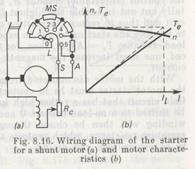
The wiring diagram of a starter for shunt motors is shown in Fig. 8.16a. The starter has three terminals denoted by letters L, A, and S. The terminal L connects the starting lever to one of the
contacts of the power line switch. The terminal A provides connection between one of the armature terminals and the starter resistance. The terminal S connects the metal bus (shunt) arranged on the starter to the field winding through a control resistor Rc. The starting lever slides on the bus so that it always contacts the bus. The rest of the terminals of the armature and field windings are joined together with a jumper and connected to the other contact of a knife switch.
At starting, the switch is thrown in and the lever is moved to contact 1 to connect the armature winding in series with all the starting resistance of the motor starter MS, the value of which is so chosen that the maximum current Imax is not more than 1.7 to 2.5 times the rated current, Rs = V/Imax — Ra.
With the motor switched in the line, the field winding begins to carry the current exciting the magnetic flux. This flux reacts with the armature current, thus developing the starting torque.
If the starting torque Ts proves higher than the braking torque Tb of the load on the motor shaft, the armature begins to revolve. Because of inertia, the motor will not gain speed instantly but will accelerate gradually. As the motor continues to pick up speed, its counter emf builds up and the armature current falls off, causing the motor torque to decrease.
In the running condition, the starting resistance must be cut out completely because the starter is designed for short-time operation and may fail if the current passes through it for a long time.
When the armature current drops to Imin, the lever is pushed farther to contact 2 to reduce the starter resistance stepwise by a certain value and thus to increase the current. The resistances in all the steps of the motor starter must be such that the armature current can vary from Imin to Imax when moving the lever from one contact to the next.
As the armature current rises, so does the torque. The speed then grows, accompanied by an increase in the counter emf which tends to reduce the armature current. When this current drops to the lowest value, the lever is moved to contact 3. The starter resistance is thus reduced in steps until it is cut out completely when the lever is pushed to contact 5. In the running condition, the armature current and speed reach steady values corresponding to the braking torque of the load.
The lowest current at starting depends on the shaft load. If the* motor starts at its full load, then Imin = 1.1 Iг. If it carries no load or a small load at starting, this current can be lower than the rated current.
The number of resistance steps of the motor starter depends on the difference Imax–Imin. The lower the difference between these-currents, the greater is the number of steps. A motor starter commonly has from 2 to 7 resistance steps. During the starting cycle, the control (adjustable) resistor Rc in the field circuit must be totally cut out to enable the highest field current to flow in the circuit and thus to reduce the starting current. Besides, it is necessary to produce the starting torque in excess of the resisting torque of the load. Because Ts = KIsΦ, then, for the starting current to be reduced, one must increase the magnetic flux by stepping up the field current.
With the motor disconnected from the supply, the metal bus of the motor starter must be in contact with terminal 1 to make the field circuit that has a rather high inductance. Also, the lever must be shifted to a no-load contact 0 and the switch cut out. The field winding will then be closed through the starting resistance and armature resistance, which protects the motor against the possibility of overvoltage and arcing.
Дата добавления: 2015-06-17; просмотров: 1068;