Speed Control of Three-Phase Induction Motors
The rotational speed of a rotor per minute is given by the expression n2 = пг (1 - S) = 60f1(1 — S)/p. It is apparent from this expression that the motor speed can be controlled by adjusting any of the three parameters that determine the speed, namely, supply frequency f1 number of pole pairs p, and slip S.
Control by changing the frequency of the supply system is impractical or complex because this method necessitates an adjustable frequency converter or a generator. Therefore, this method of control finds limited uses.
Control by changing the number of poles can be made if the stator carries a few (commonly two) windings which are wound for different numbers of poles or a single winding arranged for reconnection to form the desired number of poles, or two windings each of which can be connected to form a different number of poles.
Figure 7.11a illustrates two coils of one phase, connected in series. The current flowing through the coils produces a magnetic field with four poles. Connecting one of the coils in opposition to the other to reverse the direction of current in it enables the winding
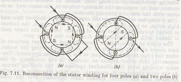
to produce a two-pole magnetic field (Fig. 7.116). A change in the number of poles of the stator winding changes the rotational speed of the stator field and, hence, the speed of the rotor. This method of speed control is economical, but presents the drawback in that it changes the speed in a stepwise manner. Besides, the motor with such a speed control is rather costly because of a complicated stator winding and increased size of the machine.
Speed control by changing the number of poles applies to squirrel-cage motors. For wound-rotor motors this method is impractical since it calls for reconnecting both the stator winding and the rotor winding for the desired number of poles, which makes the circuit arrangement rather complex.
Soviet industry produces four-speed two-winding motors adjustable for synchronous speeds of 500, 750, 1 000, and 1 500 rpm. Each of the two stator windings can be reconnected for one of the two speeds.
Speed control by changing the slip relies on an adjustable resistor (rheostat) introduced into the rotor circuit. The slip can also be changed by varying the voltage of the power line. The line voltage adjusted for the desired value causes the rotor torque to vary as the square of the impressed voltage. As the torque decreases, the rotor begins to slow down, i.e. the slip grows.
An adjustable resistor is inserted into the wound-rotor circuit in the same way as a starting rheostat, but the former is designed to carry the current for a long time. The adjustable resistor connected to the rotor circuit decreases the rotor current. This, in turn, reduces the motor torque and, hence, the rotor speed, or increases the slip. An increase in the slip causes the rotor emf and current to grow. The speed and slip will vary until the torques come to equilibrium, i.e. until the rotor current reaches its initial value. This method of speed control is only applicable to wound-rotor motors and finds wide uses despite the fact that it is open to the objection because the adjustable resistor increases the copper loss and reduces the efficiency.
Дата добавления: 2015-06-17; просмотров: 1158;