Operation of the DC Machine as a Generator
The armature of a generator is set into rotational motion by a driver developing a torque T1. When the conductors of the armature winding cut the magnetic field of poles, the emf is generated in the conductors, the direction of which is defined by the right-hand rule (Fig. 8.10). If the armature revolves at a speed n per minute, the emf generated in the armature winding is Е=спФ.
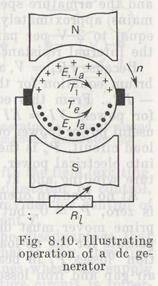 When the armature winding supplies a resistive load Rl through the brushes, the current I flows in the external circuit, the direction of which in the armature winding is the same as that of emf. This current interacts with the magnetic field to produce an electromagnetic torque Te whose direction is found by applying the left-hand rule.
The torque Te developed by the machine is a braking torque opposing the torque of the armature, for which reason, in order that the armature should revolve at the rated speed, the prime mover must produce a sufficient torque T1 enough to overcome Te. The machine thus consumes the mechanical energy.
When the torques are equal, T1 = Te, the armature revolves at a constant speed, otherwise its speed begins to change. If the torque of the prime mover becomes lower than the electromagnetic torque of the generator, T1 < Te, the armature begins to slow down, accompanied by a decrease in both the emf and current in the armature, with the result that the braking torque Te falls off. If T1 becomes higher than Te, T1 > Te, the armature speed and also the armature emf and current will rise, which will cause Te to increase.
When the torques are put out of balance, the armature speed and the armature emf and current undergo changes until T1 becomes equal to Te.
Thus, any changes in the torque of a prime mover, i.e. in the power absorbed by the generator, cause corresponding changes in both the electromagnetic torque and the power produced by the generator. Also, changes in the load on the generator necessitate corresponding changes in the prime mover torque to keep the armature speed constant.
The armature current of the generator under load meets on its way the opposition to its flow, namely, the external load resistance Rl armature winding resistance Rw, and contact resistance Rc between brushes and commutator. Denoting the internal (armature) resistance of the machine by Ra, which is the sum of Rw and Rc, the expression for the armature current can be written as I = E/(Ra + Rl).
The resistance Rc is not constant and depends on a number of factors: the magnitude and direction of current, the commutator state, the force at which the brushes bear up against the commutator,, and the armature speed. The voltage drop across brush contacts remains approximately invariable with load changes and is taken equal to 2 V per pair of carbon and graphite brushes. Therefore, the internal resistance varies with loads.
Because IRl = V, where V is the load terminal voltage, the equilibrium equation for the generator voltage takes the form V = E — IRa. From this equation we can readily derive the expression for powers VI = EI— I2Ra or P2 = Pe — Pa, where P2 is the-useful power (power output) delivered by the generator to an external load circuit, Pe is the internal, or electromagnetic, power converted into electrical power, and I2Ra = Pa is the power lost in the armature winding and at brush contacts.
At no load (in open-circuit conditions), the electromagnetic power is zero, Pe = 0, but for the armature to be held in motion, the-prime mover must deliver a certain amount of power Po to compensate for the no-load power loss. The power Po is the sum of friction losses Pf in bearings, at the commutator surface, and in th& air gap and iron losses Pir due to hysteresis and eddy currents. In-self-excited generators the power Po also includes the power required to produce the magnetic flux, i.e. to excite the machine. When a generator operates into a load, the prime mover expends a power P1 = Pe + Po.
The electromagnetic torque of a machine is Te = Pev, where v = 2πn/60 in rad/s is the angular velocity. Since Pe = EI and E = (pN/60a) пΦ, the expression for Te assumes the form Te = (pN/2πa) IΦ.
The parameters p, N, and a are constant for a given machine, therefore the ratio pN/2πa is a constant coefficient K. The torque Te is then given by the expression Te — К1Φ.
Both permanent magnets and electromagnets can provide excitation for dc generators. Permanent magnet generators are small-power machines. Medium and large generators employ electromagnetic excitation for producing the magnetic flux by the current flowing in the field winding.
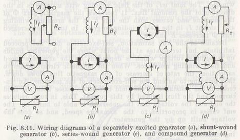
Depending on the method of supplying current to the field winding, dc generators can be of the separately excited and self-excited types. In the method of separate excitation, [as illustrated in Fig. 8.11a, the field (exciting) winding is fed with the field (exciting current If from an auxiliary dc source. The adjustable, or control, resistance Rc inserted into the feed circuit provides for control of If which is independent of the armature current I.
Separately excited generators suffer from the disadvantage that they require an additional source of energy. That is why, they find very limited uses, only as high-voltage machines where the supply of power to the field winding from the armature circuit is impermissible from design considerations.
Self-excited generators fall into several groups depending on the types of connection of field windings: shunt-wound (Fig. 8.11b), series-wound (Fig. 8.11c), and compound generators (Fig. 8. lid).
In shunt generators the field current is small, only a few percent of the rated armature current, and the field winding is wound with a large number of turns. With series excitation, the field current is equal to the armature current and the field winding consists of a small number of turns. With compound excitation, a parallel and a series field winding are wound on the generator poles.
The process of self-excitation of dc generators is the same irrespective of the type of excitation circuit. For example, in a shunt generator, which is the most popular machine, self excitation proceeds in the following manner. Assume a driver sets in motion the generator armature whose magnetic circuit comprising the frame (yoke) and pole cores has a small residual flux Φres. This flux generates an emf Eres in the armature winding, which is only equal to a few percent of the rated voltage. This emf forces the field current If to flow in the closed circuit comprising the armature and the field winding. The mmf wIf of the field winding with w turns is in the direction of the residual flux. It increases the magnetic flux Φ of the machine and causes both the emf E in the armature winding and current If in the field winding to grow. In turn, the increased flux Ф increases E and If. . ,
Because of the iron saturation, self-excitation does not proceed infinitely, but terminates at the point where the generator builds up a definite voltage which is dependent on the armature speed and field winding resistance. When the magnetic circuit comes to saturation, the rate of increase of the magnetic flux slows down, thus bringing to an end the self-excitation of the machine. An increase in the resistance of the field circuit decreases both the field current and the flux induced by this current. Thus, in turn, reduces the emf and the voltage that the generator is able to build up. The emf varies in proportion to the armature speed, and so does the voltage built up by the generator.
Self-excitation of a generator will take place only under the following conditions.
1. The self-excited generator must have the flux of residual (remnant) magnetism. If this flux is absent, there will be no emt Eres to initiate the current flow in the field winding and the generator will not be able to build up its own voltage. To enable the demagnetized machine to acquire the residual magnetism, it is enough to pass the current through the field wiping from a separate dc source. After disconnecting the field winding, the machine will retain the residual flux.
2. The field winding must produce the flux that is in aiding relationship with the residual flux, in which case the magnetizing force of this winding will step up the residual magnetism. With the field winding connected in opposition, the winding winding mmf will reduce the residual flux and may totally demagnetize the machine operating for a long time. If the field winding proves corseted in opposing relationship, it is necessary to reverse the pair of leads coming to the winding terminals.
3. The resistance of the field circuit must not be excessively high, for, otherwise, the machine self-excitation will be impossible.
4. The external load resistance must be high because at a low resistance the field current will be too weak to be able to excite the machine.
Дата добавления: 2015-06-17; просмотров: 1222;