Commutation
By commutation is meant the reversal of generated emf in each coil every time the coil passes from one pole to the next adjacent one.
When a dc armature revolves, the commutator segments alternately contact the brushes, so that each brush closes a coil or a few coils at a certain instant. Because the contact resistance between brush and commutator segment is small, this closing is analogous to short-circuiting of the coil.
In Fig. 8.8a is shown the coil of a simplex wave winding. This coil provides one parallel path for a current flow, ia = I/2a, where I is the load current, and 2a is the number of parallel paths.
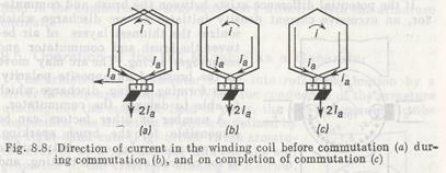
With the armature revolving, the armature winding and commutator move relative to the stationary brush from right to left. At a definite instant corresponding to the beginning of commutation, the brush comes in contact with segment 1 connected with two conductors of the coil, each carrying the current of one parallel path. Thus, the current passed through the segment and brush is equal to the sum of currents in two parallel paths, 2ia.
In the coil under consideration, the current is equal to the current in one parallel path and at the given instant flows in a counterclockwise direction.
When the armature turns further through a certain angle, the brush spans segments 1 and 2, thus shorting out the coil in question (Fig. 8.8b). An instant later, segment 1 passes out from under the brush which now contacts only segment 2, so that the current in the coil of interest reverses its direction (Fig. 8.8c). This is the way of commutation of the coil which switches over from one parallel path into the other. The time of complete reversal of the current in the coil, called the commutation period, is small and during this time the current changes from +ia to — ia. The reversal of current gives rise to the emf of self-induction, which can be appreciable.
Besides, since the process of commutation occurs simultaneously in several coils under all brushes, the emf of mutual induction appears in each coil. Both of these emfs, called reactive emfs er, oppose the reversal of current and cause a nonuniform distribution of current density under brushes. This results in sparking at the brushes, which is particularly strong at the instant when the brush disconnects the coil.
 If the potential difference exists between the brush and commutator, an excessive current density initiates an arc discharge which
ionizes the thinnest layers of air between the brush and commutator and encourages arcing. The arc may move to the brush of an opposite polarity, thus forming a ring discharge which is able to damage the commutator.
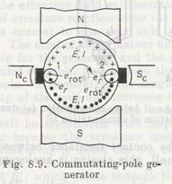
A number of other factors can be responsible for the brush sparking, such as an irregular or a dirty surface of the commutator, brush beating, and moisture on the commutator surface. Even an insignificant sparking at the brushes is undesirable since it brings about rapid wear of the brushes and commutator and also heavily heats sup the commutator because of the increased contact resistance. The most effective way of improving commutation is to compensate for the reactive emfs. For this, in the commutation zone where the face sides of the commutated coils travel, one must produce such an external magnetic field that the rotational emf erot generated in the coils can be equal and in opposition to the reactive emf er, erot = —er. Commutating poles Nc and Sc, or interpoles, mounted on the frame between the main poles provide for such a field.
If the armature of the generator illustrated in Fig. 8.9 is driven by a prime mover causing it to revolve in the clockwise sense, the emf is induced in the armature winding, which forces the current to flow into an external load circuit. The emf and current are in the same direction. The figure demonstrates conductors 1 and 2 of the coil undergoing commutation. The reactive emf er opposes the changes of current in the coil and thus is opposite in direction to the currents in conductors 1 and 2. To counterbalance the reactive emf in conductors 1 and 2, the poles Nc and Sc should produce the rotational emf erot that is equal to er, erot = —er.
So, the commutating pole in a generator must have the same polarity as the successive main pole in the direction of rotation. In a motor, its polarity must be the same as that of the preceding main pole in the direction of rotation.
The field winding of interpoles is placed in series with the armature winding to compensate for er at any load on the machine. For the same reason, the magnetic circuit of interpoles is made unsaturable by way of a rather large air gap provided between the armature core and interpoles. Since the reactive emf is proportional to the armature current, the emf er is made up for at any load if the rotational emf is proportional to the load current. That is why the field in the commutation zone must vary directly with the armature current.
Дата добавления: 2015-06-17; просмотров: 1065;