Armature Windings and EMF
The armature windings of dc machines are made from insulated copper wire, or from rectangular buses for large machines. Each winding consists of a number of coils connected together to form the desired closed circuit. The windings made of rectangular buses come in bar winding designs where each coil can consist of two conductors forming a one-turn coil. The coils of insulated copper wire are multiturn coils wound with a definite number of turns.
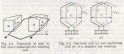
Two-layer windings find most extensive uses in dc machines. The face (effective) conductors forming the useful edges or sides of coils of this type of winding are laid in two layers in the armature slots. The spread or pitch of the coil, i.e. the distance between the opposite edges of the coil is nearly equal to the pole pitch, which is the distance between the axes of the successive unlike poles. At such a coil pitch, the opposite sides of the coil are at any instant under the poles of opposite signs and therefore generate the emfs which add in the circuit (Fig. 8.4). One conductor of the coil lies in the top side of the rotor slot, and the other conductor in the bottom half of another slot, approximately one pole pitch away. In the developed drawing of the winding, the face conductors in the upper layers are shown as solid lines, and those in the lower layers as dotted lines. The coils are connected with each other and with commutator bars.
The interconnection of coils should be such that their generated emfs are always additive. For this, the conductors of series-connected
coils, which form the paths for the current that enters or leaves the winding, should at any instant lie under the poles of the same polarity.
Depending on the kind of connection of coils, one differentiates between lap (parallel or multiple) windings and wave (series) windings.
In Fig. 8.5, the heavy lines represent a one-turn coil (a) and multiturn coil (b) of the simplex (simple) lap winding; one face side of the coil lies in the upper layer in slot 1 and the other side in the lower layer in another slot 1 + y1. In this winding the coils placed in series have their corresponding face sides lying under one pole in adjacent slots. Thus, each lap-wound coil ends on two adjacent segments 1 and 2; in the multiturn coil, the beginning of the first turn connects to segment 1, and the end of the last turn connects to segment 2 and to the beginning of the next coil. Any commutator bar, say, 1 makes connection to two face conductors, each of which carries the current ia of one parallel path of the winding, so that the winding forms two parallel paths between two brushes of opposite signs. In the lap-wound armature, the number of brushes must always be equal to the number of poles 2p; hence, the number of parallel paths 2a in the armature winding equals the number of poles, 2a = 2p or a = p.
If the number of poles is large, the lap winding forms many parallel paths. This permits the current per path to be low enough to employ the coil conductors of a reasonably small size.
In the wave winding, the beginning of one coil connected to a commutator segment is two poles distant from the coil end connected to another segment (Fig. 8.6). The coils then need be placed in series connection. The edges of the first coil are under poles N1 and S1those of the second, under N2 and S2, those of the third under N3 and S3, etc. With all the coils put in place around the armature, tracing is begun through the winding to connect the conductor of pair n to the adjacent upper conductor of pair n — 1 (commonly on the left side) and then the latter conductor and the
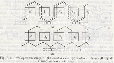
former conductor to conductors under poles Sl, N2, S2, etc. After connecting the subsequent pairs of conductors under different poles, the resultant winding becomes a closed series circuit.
Whatever the number of poles, the simplex wave winding always has only two armature paths, 2a = 2. That is why, the wave-wound armature requires only two brushes spaced at a distance equal to 1/2p of the commutator circumference. For example, at p == 2 the distance between the brushes must equal one-fourth the commutator circumference. Such an arrangement provides convenient access to the brushes for inspection over a small section of the commutator circumference. Since the wave-wound armature' has only two parallel paths for current flow and each brush shorts half the number of face conductors, the emf generated in the winding can be very large. Wave windings are used where high voltage is the primary design factor.
The emf generated in the conductor passing through the magnetic field in the direction normal to its magnetic lines is equal to e = Blv, where В is the mean of the magnetic flux density, T; l is the conductor length, m; and v is the conductor speed, m/s.
The armature of a machine has a large number of face conductors, N, embedded in its slots. Each parallel path of the winding includes N/2a series-connected conductors. The emf of the machine then is E = eN/2a = BlvN/2a.
The speed of conductors in the field is v = 2pτn/60, where 2p is the number of poles, τ is the pole pitch, and n is the rotational speed of the armature per minute.
Keeping in mind that the product of B, axial length l of the pole, and pole pitch τ is the magnetic flux per pole, Ф = Blτ, the expression for the machine emf takes on the form E = nФpN/60a.
For each machine the values of p, N, and a are constant, so the ratio pN/60a = с is a constant value. Consequently, the emf of a dc machine is given by the expression E =спФ. In words, the emf is the product of the constant design factor c, armature speed n, and flux per роle Ф. This expression reveals that the emf (voltage) of a machine can be varied by changing the armature speed or flux per pole. Since control of the emf by varying the speed of the prime mover that drives the generator involves much difficulty, a practical approach is to change the magnetic flux which depends on the field current. Control of the field current can be made by a rheostat inserted into the field circuit.
8.3. Magnetic Field of a Loaded DC Machine
At no load, the armature winding carries no load current, but the mmf of poles excites the main magnetic field which is symmetric relative to pole axis and uniformly distributed in the air gap
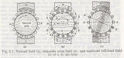
(Fig. 8.7a). Suppose the brushes lie on the no-load neutral axis А В passing through the armature center normal to the pole axis.
With the machine under load, the armature winding carries the current producing the armature field which changes and distorts the main field of poles. In other words, the mmfs of the poles and armature produce the net (resultant) flux Фnthat closes on itself through the magnetic circuit. The net flux Фn is not equal to the main flux of poles, Фm, produced at no load. The influence of the armature field in the machine under load on the main field, resulting in distortion and weakening of the main field, is known as the armature reaction.
If the armature winding of a nonexcited machine carries a load current supplied from an external source, the current will produce the armature field as illustrated in Fig. 8.7b. This is the cross field of armature reaction since the direction of its flux between the poles is normal to the pole axis.
The mmf of the armature under one tip of the pole, i.e. the leading tip for the generator and the trailing tip for the motor, opposes the mmf of poles, but adds to the pole mmf under the other tip of the pole. Consequently, the magnetic flux density decreases under one tip of the pole and increases under the other tip of the pole.
Thus, in the machine under load the resultant magnetic field will be asymmetric with respect to the pole axis (Fig. 8.76). This is because the armature cross field redistributes the main field, weakening it under one tip of the pole and increasing it under the other. The armature field also shifts the neutral line to the position A'B', which passes through the armature center normal to the mmf of the resultant field.
If the magnetic system of a machine is not saturated, then an increase in the magnetic flux under one tip of the pole will be equal to a decrease in the flux under the other tip and the resultant flux will remain invariable with changes in the amount of load.
Because machines operate in comparatively strong fields, the iron saturation will cause a lower increase in the flux under one pole tip and a heavier decrease in the flux under the other pole tip, so the resultant flux at full load will be weaker than the pole flux at no load.
Variations in the magnetic flux cause both the emf and the terminal voltage of a generator to vary. If, for example, the load current (armature current) of the generator begins to rise at an invariable field current, the magnetic flux in the machine becomes weaker under the demagnetizing effect of the armature cross field. The result is a decrease in both the emf and the terminal voltage of the generator. An approach to remedy the situation described in the above case is to increase the field current, so that the enhanced flux of poles should be enough to compensate for the demagnetizing effect of the armature reaction. In a loaded machine the voltage also decreases because of the voltage drop across the resistance of the armature winding.
Дата добавления: 2015-06-17; просмотров: 1583;