Fuel system
The extremely high airframe temperatures encountered by the A‑12 during high‑Mach cruise ruled out the use of JP‑4 as its fuel source, as it had to be carried in “wet” tanks. Instead, a bespoke fuel was designed specifically for the A‑12 and known as PF‑1 (later known as JP‑7). It was developed by Pratt & Whitney, in partnership with Ashland, Shell, and Monsanto, and remained stable despite the high temperature environment, being used first as a hydraulic fluid to activate the main and afterburner fuel nozzles before being injected into the fuel burners at over 350 degrees C and 130 psi. Such high fuel‑burn temperatures presented the design team with yet another problem, because standard electrical plugs couldn’t ignite the fuel. This was overcome by developing a unique chemical ignition system involving the chemical triethylborane (TEB). Extremely flash sensitive when oxidized, a small tank of the substance was carried onboard the aircraft and used to start or restart the engines and afterburners on the ground or in the air. To ensure that the system remained inert when not in operation, gaseous nitrogen was used to pressurize the TEB tank and power the piston that injected it into the burner cans during the ignition process, regardless of engine operating conditions. As fuel was burnt, gaseous nitrogen was also used to pressurize and render inert the fuel tanks to prevent them from being crushed as the aircraft descended to lower levels to either air refuel or land.
Development of a durable fuel tank sealant was an ongoing problem. Cruising at high Mach the airframe expanded due to thermodynamic heating. Upon descending to air refuel, the airframe cooled – a process that was considerably speeded‑up when cold fuel was pumped into the tanks from the KC‑135Q tanker at 5,000lb per minute! The pounding taken by the silicon‑based sealant invariably led to it cracking, causing fuel to leak from numerous gaps.
Air Inlet Control System (AICS)
The A‑12 also boasted a unique, highly efficient air inlet system that supplemented thrust via three components: an asymmetric mixed‑compression, variable‑geometry inlet; the J58 engine; and a convergent‑divergent blow‑indoor ejector nozzle. The AICS regulated the massively varying internal airflow throughout the aircraft’s entire flight envelope, ensuring that the engines received air at both the correct velocity and pressure.
To satisfy the J58’s voluminous appetite for air during operations at ground idle, taxiing, and take‑off, the center‑body spikes were positioned fully forward, allowing an uninterrupted flow to the engine compressor. Supplementary flow was also provided through six forward bypass doors; additionally, a reverse flow was set up through exit louvers on the spike’s center‑body and a set of variable‑area “inlet‑ports” that were regulated by an external slotted‑band, which drew air in from two sets of doors. The task of operating these doors and positioning of the electrically operated, hydraulically actuated spike was controlled by the pilot. Operating together, the forward bypass doors and the center‑body spike were used to control the position of the normal shock wave, just aft of the inlet throat. To optimize inlet efficiencies, the shock wave was captured and held inside the converging‑diverging nozzle, just behind the narrowest part of the “throat,” thereby achieving the maximum possible pressure rise across the normal shock.
Once airborne, the forward bypass doors closed automatically as the undercarriage retracted. At Mach 1.4, the doors began to modulate, again automatically in order to obtain a pre‑programed ratio between “dynamic” pressure at the inlet cowl on one side of the “throat” and “static” duct pressure on the other side. Upon reaching 30,000ft, the inlet spike unlocked and at Mach 1.6 began a rearward translation, achieving its fully aft position of 26 inches at Mach 3.2 – the inlet’s most efficient speed. As the spike moved aft, the “capture‑air‑stream‑tube‑area” increased by 112 percent, while the “throat” restriction decreased by 46 percent of its former size. A peripheral “shock trap” bleed slot (positioned around the outer circumference of the duct, just forward of the “throat” set at two boundary‑layer displacement thicknesses) “shaved” off 7 percent of the stagnant inlet airflow and stabilized the terminal (normal) shock. It was then rammed across the bypass plenum through 32 shock trap tubes spaced at regular intervals around the circumference of the shock trap. As this air was compressed, tertiary air traveled down the secondary bypass passage, firmly closed the suck‑in doors, and cooled the exterior of the engine casing before being exhausted through the ejector nozzle.
Potentially turbulent boundary layer air was removed from the surface of the center‑body spike at the point of its maximum diameter and then ducted through the spike’s hollow support struts, before being dumped overboard through nacelle exit louvers. The aft bypass doors were opened at mid‑Mach to minimize the aerodynamic drag that resulted from dumping air overboard through the forward bypass doors. By carefully dovetailing all the above parameters, the inlet was able to generate internal duct pressures of 18lb per square inch; when this is considered against the ambient air pressure at 82,000ft of just 0.4lb per square inch, it is immediately apparent that this extremely large pressure gradient is capable of producing a similarly large forward thrust vector. In fact, at Mach cruise this accounted for no less than 54 percent of the total thrust being produced; a further 29 percent was produced by the ejector, while the remaining 17 percent was generated by the J58 engine. If, however, airflow disturbances disrupted this delicate pressure‑balancing trick, it is equally easy to appreciate the effects that such excursions would have upon the aircraft.
This brings us to yet another of the A‑12’s unique idiosyncrasies: the “unstart.” These unstarts, or aerodynamic disruptions (ADs), occurred when the normal shock wave was “belched” forward from the inlet throat, causing an instant drop in the inlet pressure and thrust. With each engine positioned at mid‑semi‑span, the shock wave departure manifested itself in a vicious yaw in the direction of the “unstarted” engine; sometimes these were so strong that crewmembers would have their helmets knocked against the cockpit canopy framing. Recovery from such an incident required the pilot to re‑sequence the inlet in order to get it restarted. This involved the spike being driven forward and opening the forward bypass doors to recapture and reposition the shock wave. The spike was then returned to its correct position, followed by the bypass doors, which reconfigured the inlet to its optimum performance. “Unstarts” were a regular feature of early A‑12 flights, but as computer software improved a system known as the Digital Automatic Flight and Inlet Control System (DAFICS) was developed for the SR‑71. The DAFICS was able to achieve near‑perfect inlet airflow control, which in turn practically rid the jet of its “unstart” problems.
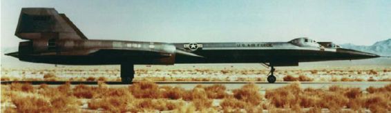
The two‑seat AT‑12T dedicated pilot trainer was powered throughout its life by two Pratt & Whitney J75 engines, which were considerably less powerful than the twin J58s that equipped the single‑seat variant. The trainer therefore lacked the ability to cruise at Mach 3+. (Lockheed Martin)
Дата добавления: 2015-05-08; просмотров: 1213;