Stability Augmentation System
The A‑12’s center of gravity (CG) was automatically moved aft during acceleration to high‑Mach flight, to reduce trim drag and improve elevon authority in both the pitch and roll axes. The fuselage chine produced lift forward of the center of gravity, which had the effect of destabilizing the aircraft in the pitch axis and reducing aft CG travel, resulting in low static margins of stability and safety. Additionally, the chine had an adverse aerodynamic effect on the aircraft when performing sideslip maneuvers at cruise angles of attack (approximately 6 degrees of positive alpha). This, coupled with low aerodynamic damping – inherent with flight at high altitudes – conspired to make the A‑12 only marginally stable in both pitch and yaw at high Mach.
Control in this delicate but critical corner of the flight envelope was achieved by the aircraft’s elevons and rudders, which were worked through an automatic flight control system (AFCS). The AFCS consisted of a redundant three‑axis stability augmentation system (SAS), a two‑axis autopilot, an air data computer, and a Mach trim system. Other associated equipment included an inertial navigation system (INS), a flight reference system (FRS), hydraulic servos, and a pitch actuator. The AFCS provided pitch, roll, and yaw stabilization via the flight control surfaces. Eight rate‑sensing gyros detected divergence from stable flight and together with three lateral accelerometers, also provided motion‑sensing signals relative to the rate of change in all three of the aircraft’s axes, thus damping excessive changes in attitude. Because these SAS corrections were applied through a series of servos, they weren’t apparent to the pilot at the control stick or rudder. Control over the AFCS was provided to the pilot via “Pitch SAS,” “Roll SAS,” and “Yaw SAS” switches, located on the right‑console panel. The servos could also be activated by direct stick and rudder‑pedal inputs.
The two‑channel (pitch and roll) autopilot processed INS and FRS inputs, then applied the data through the SAS electronics to transfer valves for control surface positioning. This provided the autopilot with two separate “hold functions.” Pitch control was achieved via the basic attitude hold mode, Knots Equivalent Airspeed “hold,” or Mach “hold.” In roll mode, control was exercised via the basic roll attitude hold mode, heading hold mode, or auto‑steering “Auto Nav” mode; this latter mode was programed to obey heading commands from the INS. When the autopilot was engaged, the aircraft was held in the roll attitude established at the time of engagement. With “Auto Nav” selected, the autopilot controlled roll to ensure that the aircraft adhered to the predetermined navigation track that the INS accurately maintained. During operational sorties the aircraft was invariably flown in this mode to ensure that it remained stable and on an accurate track whilst the onboard sensors were activated.
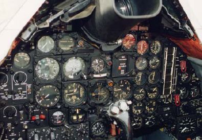
Although the A‑12 was highly advanced, the cockpit instrumentation and its layout were very unspectacular and straightforward. The hooded view scope can be seen at the top of the picture. (Roadrunners Internationale)
The Mach trim system provided speed stability up to Mach 1.5, while the aircraft was either accelerating or decelerating – a period during which the autopilot could not be engaged. It compensated, via the pitch trim actuator, for the aircraft’s propensity to “tuck” nose‑down while accelerating through the Mach and rise nose‑up while decelerating.
Inertial Navigation System (INS)
The A‑12’s INS was completely self‑contained and provided the principal navigation references to the aircraft without recourse to any electromagnetic radiation or other external references. The system provided attitude, true heading, command course, ground speed, distance, and geographic position data for automatic or manual navigation between waypoints on the flight plan. The pilot could, if required, update position information periodically to correct gyro drift by taking fixes with a view scope that provided an optical display of the terrain along the flight path, or by taking sun fixes with an optical device to measure the sun azimuth angles for determination of true heading.
The flight reference system provided magnetic heading information and served as an alternate navigation reference. A gyromagnetic compass provided both slaved gyro and free gyro heading information, while a gyro platform provided pitch and roll information.
A set of integrated flight instruments consisting of an attitude indicator, a bearing‑distance‑heading indicator and related signal‑switching equipment, displayed navigation information to the pilot. The indicators operated in conjunction with the inertial navigation and flight reference system to provide data to the pilot.
Дата добавления: 2015-05-08; просмотров: 1610;