Experimental part. An experimental device to measure the resistance consists of the column with wire and measuring block (fig.8.4).
An experimental device to measure the resistance consists of the column with wire and measuring block (fig.8.4).
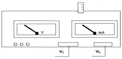
Figure 8.4
On the column there are two motionless brackets and a traveling one which can move along the column and be fixed in any position. The mark which is drawn between the upper and the lower brackets facilitates to define the length of the segment of resisting wire being measured.
The measuring part is placed in the separate block which has milliamperemeter, voltmeter and operating keys. Milliamperemeter is plugged in the resisting wire circle and used to measure the current and voltmeter to measure the voltage in the measured length of resisting wire. The switch W1 is used to choose the type of work and the switch W2 to choose the accuracy of current and voltage measurement.
1. Move the traveling bracket for 0,7 - 0,8 of length of the resisting wire, take it from the basis.
2. Press button W1 “МЕРЕЖА”.
3. Press button W3“МІСТОК”.
4. When pressing button W2 the scheme works in the Fig. 8.5.
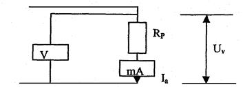
Figure 8.5
5. Write down the measurements which shows millliamperemeter and voltmeter and calculate R using the formula  , Ra= 0,15 Om, Ra = 2500 Om.
6. When pressing button W2, the scheme in the Fig. 8.6 works.
7. Make measurements of the millliamperemeter and voltmeter readings and calculate R using the formula:
 ,
,  .
.
Figure 8.6
8. Measure with micrometer the diameter of the wire d, the length of the wire from the basis to the traveling contact l, calculate the specific resistance r using the formula
 .
.
9. Using one of the schemes of connection build up the constant value of the current I with the help of regulator. Moving the traveling contact of the resisting wire for a few marks find 8-10 values of the U.
10. Count 8-10 values of R using the formula which correspond to the switching on scheme.
11. Fill in the table with data:
| № | |||||||||
| Ia, A | |||||||||
| I, m | |||||||||
| Uv,V | |||||||||
| Rp, Om |
12. Build up the graph Rp =f(I).
13. Count the error for Rp . Make a conclusion about the work done.
Дата добавления: 2015-03-20; просмотров: 763;