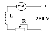
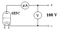
Experimental part. The wiring scheme is shown in Fig
The wiring scheme is shown in Fig. 15.2:


Figure 15.2
When current doesn't flow through the solenoid the anode current of the electron tube will be maximum. If current begins to flow through the solenoid and increases the anode current will decrease.
The anode current equal to zero corresponds to Icr (Fig. 15.3).
2. The handle of voltage control is in the left position of the front panel of the current source ВУП-2. This handle must be in the position "0" when the source of current is turned off.
3. Switch on the source of current.
 4. Write the value of the anode current Ia and voltage U when the solenoid current is absent and when the electron tube is being heated.
5. Increase the solenoid current from "0" to max value and write down the values of the anode current in the table.
6. Plot the graph of Ia = f(IL).
Figure 15.3
7. Define the Icr on this graph.
8. Calculate e/m by the formula (15.1), where m0 = 4p × 10-7 H/m,
n = 5 × 10⁴ 1/m, R = 5 × 10⁻³ m.
This instruction is worked out by S. Lushchin, reader of the physics chair.
Reviewer: S. Loskutov, professor of the physics chair.
Дата добавления: 2015-03-20; просмотров: 769;
