Tracing of plumbing network
External plumbing networks
Tracing of plumbing network
Under tracing of plumbing network understood determination of street collectors placement on the settlement scheme. Main task during network tracing consists in leading away sewer on pipes and channels by self-flowing from the maximum possible territory.
Immediately before tracing territory, which is plumbs, is divided into pools, choose places of clearing constructions and leading away of drain waters placement. Borders of sewerage pools are determined by the relief of locality and project of the vertical planning. Borders of pools, as usual, coincide with lines of watersheds. Location places of clearing constructions are chosen lower than settlement by the flow of the water with providing of sanitary-technical zone for the border of living building.
Tracing of the network depends on significant number of factors. During tracing of the sewage network it is necessary take into consideration:
a) Relief of the locality for decreasing of pipes deeping and possibility drain waters leading away by the method of self-flow; b) location of clearing constructions; c) marked place of drain liquid output to the basin; d) ready sewerage network; e) character of quarter building; f) order of priority of building.
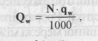
Sewage networks in the centre of the pool are traced from watershed to thalwegs. As a rule, street collectors are projected perpendicularly to horizontals of the locality in direction of lower places of the pool. Main collectors often directed along river banks. Through the main collector drain liquid is leaded away beyond limits of the settlement. Tracing of the street sewage networks mau be realized by three chief schemes.
1) Scheme from lower side of the block is applied with defined relief with falling of the level of the ground to one or two facets of the block (inclination of the ground surface is more than 0,008-0,01). Street networks in that case are constructed only on passage near lower sides of the block.
2) Covering scheme is applied with plate relief of locality (inclination up to 0,005-0,007), big sizes of blocks and absence of building inside of blocks. Street networks are constructed on passages, which cover block from all sides.
3) Through-block scheme foresee s that street networks are constructed inside of blocks – from higher located to lower located, which allows to decrease length of sewage network and cost of their building. But application of this scheme requires accurate coordinate of building of block and complicates network exploitation.
Plumbing lines should be putted straight-linearly. In places of network turnings, in places of inclination lines and pipes diameter change, and also in places of a few lines connection should be installed wells. During projecting of the sewage network trace, should be avoid or reduced number of crossings with railway rut, underground constructions and water barriers, because installation of these crossings is complicated and causes difficulties of exploitation.
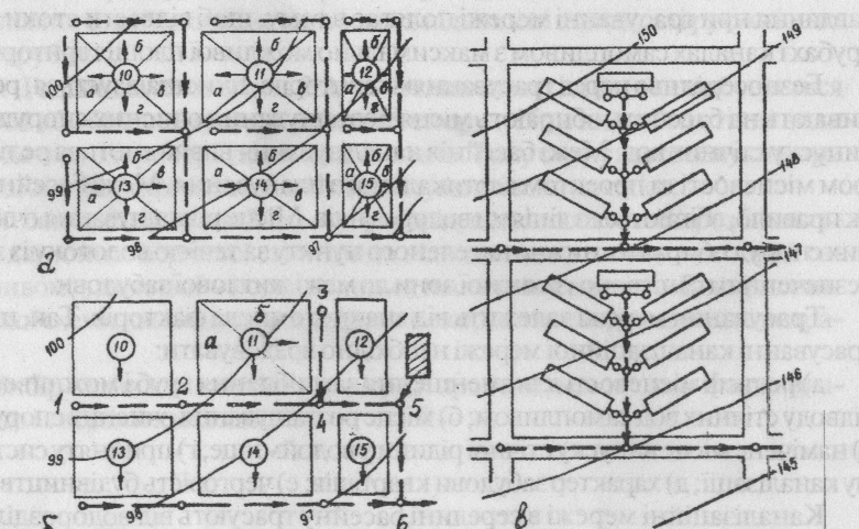
Drawing 2.3. Schemes of sewage network tracing: a) by covering scheme; b) from lower parts of blocks; c) through-block; a, b, c, d – block’s sectors, 10-15 blocks numbers; 1-6 nodes wells.
2.2.2. Fundamental data for networks projecting
Fundamental data for treatment of project of sewaging of the settlement or industrial enterprise serves master-plan of the settlement or enterprise, which takes into consideration perspective of its development.
Sewage is projected for all calculation period, during which networks should have certain capacity and conform to its intention without reconstruction and widening. For cities this period is 20-25 years, and for industrial enterprises it is equal to term, during which they will work on full power.
Besides the project of the maser-plan of building of city or enterprise for projecting of the sewage system are needed such materials:
a. Lists about placement of population and its number for perspective;
b. Limits of the sewaging territory;
c. Characteristics of public welfare f the settlement and sanitary evaluation of the locality;
d. Hydrological and geological data of the territory;
e. Hydrological data of the closed water objects;
f. Meteorological data;
g. Characteristics of natural and engineering-building conditions, building and raw bases.
Project of the system of sewage are executed accordingly to acting norm documents, in which are given rules of sewage system choice, norm materials for determination of calculation losses of drain waters and sizes of sewage construction, hydraulical calculation of the networks and equipment, technological calculation of cleaning constructions etc.
2.2.3. Norms and regime of water drainage. Calculational expenses of drain waters.
For determination of drain waters for the end of calculation period are needed lists about number of population and data about enterprises.
Calculational number of citizens N is determined dependently on density of population of the given block (region):
N=pF (2.1)
Where F – territory of the region (block), which is sewaged, ha; p- number of citizens, which are living on 1 ha of the region area – density of population, men/ha.
Density of population in cities and settlements of the city type varies in dependence on superficiality of building from 50 to 700 persons per 1 ha of the area.
Expenses of everyday drain waters depends on norms of water drainage and number of habitants, which use sewage; expanses of industrial drain waters – from norm of industrial water leading-away and number of production. Norm of water drainage are called expenses of drain waters, l/day, for one habitant, which uses sewage, or number of drain waters, m3, per production unit, which enterprise produced. Norm of water drainage for settlements is equal to norm of water consumption and may be taken in limits 125-250 l/day (table 2.1). Leading away of everyday drain waters from industrial enterprises should be taken into account separately (table 2.2). During determination of norms of water leading-away of industrial drainages are used technologists data, and while determination of norms of water drainage from separate buildings and constructions of special intention – norms of projecting of internal plumbing and sewage.
Table 2.1
Norms of water drainage from regions of habited building
| Degree of welfare of regions of habited building | Norm of water drainage per one habitant, average day (behind year), q, l/day |
| Building by houses, equipped by internal plumbing and sewage, without baths | 125-160 |
| Building by houses, equipped by internal plumbing, sewage and baths with local water heaters | 160-230 |
| Building by houses, equipped by internal plumbing, sewage, and system of central water provision | 230-350 |
Notes:
1. Norms of water water drainage should require to accepted for certain object to norms of water-supply
2. In non-sewaged regions nom of water drainage should be accepted as 25 l/day for one habitant
3. Number of drain waters from enterprises of local industry, and also not taken into account expanses allowed to take additionally in size 5-10 % from summary quantity of drain water of the settlement.
Table 2.2. Norms of water drainage of everyday drain waters of industrial enterprises.
| Type of workshops | Norms of water drainage for one worker per shift, l | Coefficient of hour non-uniformity of water drainage |
| In workshops with significant heat secretion (more than 23,2 Vt/m3*hour) | ||
| In other aims | 2,5 |
Drain waters comes to sewage network non-uniformly as in separate days as in separate hours of the day. Non-uniformity of its coming characterized be power graph, analogical to corresponding graph of water consumption ( dr.1.28).
Calculation hour and second expenses of water are determined by common coefficient of non-uniformity of drain water income, K, which depends on average expenses of everyday drain waters:
| Q | |||||||||
| K | 2,5 | 2,1 | 1,9 | 1,7 | 1,6 | 1,55 | 1,5 | 1,47 | 1,44 |
Expenses of everyday drain waters are determined by formulas:
Average-day (2.2)
Maximum-day (2.3)
Maximum-hour (2.4)
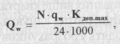
Maximum-second (2.5)
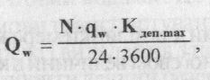
Where N – calculational quantity of habitants; q – average-day norm of water drainage, l/day; K – 1,1-1,3 – coefficient of day non-uniformity of drain waters coming.
Average-day, m3/day, and maximum-second, l/sec, expanses of productional drain waters calculated by formulas:
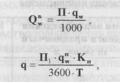
Where P – number of production, which is produced per day; P1 – same in the shift of max productivity; q – norm of water drainage of productional drain waters per unit of production; K – coefficient of non-uniformity of production drain waters coming.
On practice sewage systems constructed accordingly to maximum second drain waters losses. It is convenient to determine calculational expenses by modulus of drainage, q. Drainage modulus – are expenses in l/sec, which are determined for 1 ha of building area:
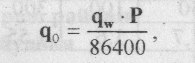
Where p- density of population per 1 ha; q –norm of water drainage, l/day.
Modulus of drainage is determined for each block, which differs from other by population density and water drainsge norm.
Before performing of hydraulics calculation of sewage network it divided into calculation parts. Calculational part of the network is called part of sewage line between two points (wells), on which calculational expenses are taken as constant.
Estimated costs for the area defined as the amount of expenses:
- Road - to arrive at the estimated area from residential building, located along the plot;
-Transit - from blocks located above;
- Side- from side lines which connected;
- Concentrated, which come in a settlement area network from some large water consumers (for example, industrial enterprises).
Track costs are variables for the network. They grow from zero at the beginning of the plot to its full value at the end reasonably connections and quarterly networks. To simplify calculations conventionally think that all traveling costs from residential blocks coming soon only to the starting point of the area. This road magnitude costs for calculation areas of street sewage network are determined dependingly on its place in the plan.
In covering scheme to calculation area receives sewage waters from an area of the quarter, which is adjacent to this area and determined by dividing of the block by bisekrtix. When mapping a network from low part of the quarter or at through-block scheme wastewater coming to the area from all areas of the quarter located above the estimated network area.
The calculations determine the cost of water perform, usually in table form (Table 2.3).
Results of calculations of expenses of drain waters for network, which is given on the drawing 2.3b
| Calculation areas | Blocks numbers | Area of flow, ha | Modulus of flow, l/sec | Average expenses of flows from blocks, l/sec | Coefficient of non-uniformity of drain waters coming | Calculational expenses of drain waters | ||||||
| road | tributary | road | transit | summary | Everyday drain waters | local | transit | total | ||||
| 1-2 | - | 0,6 | 3,6 | - | 3,6 | 2,50 | 9,0 | - | - | 9,0 | ||
| 2-3 | 11a | 4+6 | 0,6 | 2,4 | 3,6 | 2,42 | 14,5 | - | - | 14,5 | ||
| 3-4 | 11б | - | 0,6 | 2,4 | - | 2,4 | 2,50 | 6,0 | - | - | 6,0 | |
| 4-5 | 10,11 | 3+14 | 0,6 | 1,8 | 8,4 | 10,2 | 2,10 | 21,4 | - | - | 21,4 | |
| 5-6 | - | 10,11,12 | 0,6 | - | 10,2 | 10,2 | 2,10 | 21,4 | - | 37,4 |
2.2.4. Hydraulic calculation of sewer networks
Hydraulic calculation of sewerage network consist in to choose for known water consumption diameter pipe and pick up such inclination, in which the velocity of flow would be sufficient for transiti of pollution, moving with the flow. Movement of sewage canal network can be pressured or non-pressured.
Household sewage gravity network rely on incomplete filling sewage pipes. It allows to create the most favorable conditions for hydraulic transport of suspended solids, ensurer ventilation of network and removing from it harm and explosive gases and create a pool of cross-section of pipe to pass emergency spending calculation of additional wastewater.
Filling is the ratio of the height of the layer oxen in the tube (h) to the diameter of the pipe (d). It is recommended to accept such calculation filling of tubes depending on their diameter:
| D,mm | 150-250 | 300-400 | 450-900 | More than 1000 |
| h/d, no more | 0,6 | 0,7 | 0,75 | 0,8 |
For pipelines and storm drain total planned sewage should be taken full con-filling pipes at maximum cost.
When counting household sewage pipes filling velocity 'waste shall not be less than:
| D,mm | 150-200 | 300-400 | 450-500 | 600-800 | 900-1200 | |
| V min, m/s | 0,7 | 0,8 | 0,9 | 1,0 | 1,15 | 1,3 |
The largest estimated speed of wastewater should be taken: 8 m / s for metal-pipe and 4 m / s, for non-metallic. For rain sewage allowed 7 m / sec.
For hydraulic network calculation using the formulas of uniform movement (2.9; 2.10)
' 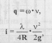
Where q - the cost of waste water, m3 / s, w - a living area of cross section, m; V - average velocity of the water m / s, and = L / and - hydraulic bow that is in uniform motion is bow feeder pipes; l-factor of hydrolic friction, I = S / s - hydraulic radius, m, s - hydraulic perimeter, m; g - acceleration of gravity, m/s2.
The coefficient of hydraulic friction is recommended to define as (2.11):
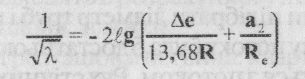
Where delta e – equivalent stiffness, cm; a – coefficient, depending on pipes stiffness.
On practice during hydraulic calculations performing of sewage pipes formulas are used comparingly rarely, and mainly used graphs, nomogramms, tables, composed by these formulas.
Minimal diameters of pipes of self-float sewage: for street network 200 mm, for yard and blocks – 150 mm, for rain and total-flow street network – 250 mm, rain block – 200 mm.
2.2.5 Sewage plumbing deepin
Cost and terms of sewagy construction significantly dependent on hollow tubes, which prescribe the minimum possible, taking into account the following requirements:
-To prevent freezing of sewage in the pipes;
-Protecting pipes from mechanical damage;
-Enable connection to street network to the yard and internal block networks.
If no data on the operation of sewage in the Construction region or in similar conditions, the smallest recess tray of pipes in their diameter to 500 mm made of 0.3 m less than the greatest depth of frosting of soil in the area, and at larger diameters-at 0, 5 m but not less than 0.7 m to the top of the pipe. Placing tubes in the freezing soil layer is allowed so that the temperature of waste water does not fall below 7 ° C even the coldest seasons.
For prevention of recompence of sewage networks by above-ground transport, usually, taken minimal deping of pipes of yard and block network in 0,7 m, and city street networks – 1,5 m from pipe top.
Initial penetration of street network determined taking into account connectivity yard or quarterly network by the formula (Figure 2.4):
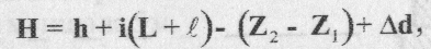
where h is least deeping of tubes in the most remote and unprofitable wells located yard network; i - bow pipe yard or quarterly network, (L + l)- length of yard or block network from far well to place of connection to street network; Z2, Z1 -marks of the ground surface near the well outside and most distant yard well, and delta d - the difference in diameters of pipelines of street and quarterly network at their connection.
Most hollow tubes in the construction of the open method take within 5 - 8 m depending on the type of soil, level of ground waters standing and other factors. When closed methods of work depth of pipes lying virtually unlimited. However, it should be remembered that the cost of building pipelines closed means a relatively large and therefore should limit the penetration of pipes.
Distance in plan between pipelines and underground parts of the buildings and other underground structures adopted for the pressure pipe not less than 5 m and for gravity - 3 m. The open method of laying pipe this distance should not be less than defined by the following formula (2.13):
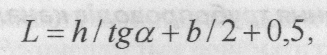
where h - distance in height between the sole foundation talotkom pipes, and tg a- slope angle (with trenches without attachment); b-width of the trench, the city
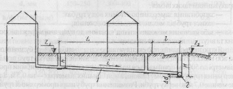
Fig. 2.4. The procedure for determining the depth of the original street network: 1 – in-block network; 2-street network.
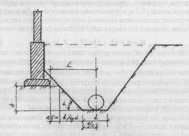
Draw. 2.5. The procedure for determining the distance between the building foundation and drainage pipeline
The design and construction obviously connected with sewage networks with other underground utilities:
• to heating lines -1.0 - 1.5 m;
• to power lines to 35 kV - • 5 m;
• for power transmission lines over 35 kV - 1.0 m;
• to the valuable species of trees, 2.0 m;
• to masts and towers are lighting, communications, contact network -1.5 m.
• to the airborne stone roads -1.5 m;
• to the edge of a ditch, 1.0 m;
• to the tram tracks and factory -1.5 m;
• to tracks the overall network-4m (to the axis lines);
• to-foot embankment at least the depth of the trench.
The minimum distance between the drainage network in parallel and pipeline laying accepted depending on the gas pressure in gas pipeline:
• at low pressure to 5 kPa - 1.0 m;
• the average pressure to 0.3 MPa - 1.5 m;
• at high pressures up to 0.6 mi IA - 2.0 m;
• at high pressures to 1.2 MPa-5m.
The minimum distance between the drainage network and water supply shall be taken;
• In a parallel routing at one level and water pipeline diameter 200 mm, not less than 1.5 m, with a larger diameter is not less than 3 m;
• The routing of the drainage network above the water supply by 0.5 m and more - not less than 5 m.
At intersections with piped water drainage network laid below the water pipe at least 0.4 m, and in cases when network is laid above the water pipe, plumbing should be protected with case.
Length of protected areas on both sides of the crossing takes: in waterproof pounds (clay) is not less than 3 m, in filtering - 10m.
Дата добавления: 2015-09-07; просмотров: 635;