Pipes, reservoirs and wells to sewer network
By the material of pipes, sewers and their connections put forward a number of requirements: strength, perception of burden of your soil and transport without deformation resistance: against corrosion and mechanical abrasion, smooth internal surface, waterproof, not allow seepage of wastewater into the soil (eksfidtratsiya) and groundwater in the network (infiltration). These requirements meets of the ceramic, concrete, reinforced concrete, asbest-cement, metal and plastic pipes (Figure 2.8).
Ceramic pipes are used for placement of non-pressured sewer networks; they are made of round cross section of hub, inner diameter 150 - 600 mm, length 800 - 100 mm. When connecting pipes ceramic smooth end of a tube inserted in the mouthing of the second pipe. The gap between them at 1 / 3 - 1 / 2 depth of bell hammer sealing material, and the remaining gap is filled with material which forms a lock that keeps the sealing material in the funnel. As the sealing material is recommended to use rubber rings, tarred hemp rope or strand, and as a lock-mastic asphalt, asbestos, cement (Figure 2.9a).
Recently begun to apply unions of ceramic pipes with conical rings from plastizole, which are fixed on the tube by the plant-producer. Collection of the junction can be easily performed horizontal pipe moving. When both rings locked and formed a dense and flexible joints (Fig. 2.96).
Concrete and reinforced concrete pipes manufactured pressure and non-pressured with bells or smooth edges. Concrete pipes have a diameter of 200 - 600 mm, and concrete (non-pressure) - 400 - 3500 mm. The length of pipe depends on diameter and method of manufacture.
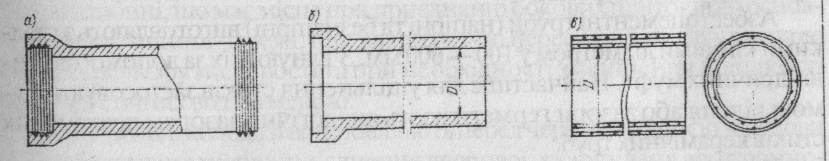
Drawing 2.8. Sewage pipes:
a) Ceramic; b) concrete bell non-pressured; c) reinforced concrete with smooth ends.
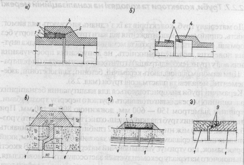
Fig. 2.9. Joints ceramic (a, b) and reinforced concrete non-pressure pipes
(C, d, e):
1 - smooth end of pipe, 2 - filling mastic asphalt or asbestos cement (cement), 3 - unglazed furrows, 4-bell, 5-tarred hemp rope or strand, 6 - cement mortar, 7 - reinforced concrete coupling, 8 - rings with plastizol, 9 - rubber ring.
Bell with 'unity of concrete and reinforced concrete pipes are carried out so as bell Connectivity ceramic tubes and pipes with smooth ends are connected by couplings or cement zones (Figure 2.9v, d). To seal the joints may be used synthetic materials, for example, polyurethane.
Asbestos cement pipes (pressure and non-pressure) are made of smooth ends with diameter 100-600 mm. Connect them using cylindrical couplings. Most often used to seal joints rubber ring or similar sealing gaps gap distribution of pipe joints of ceramic tubes.
Cast iron and steel used mainly rough day pressure sewage lines. For free-flow of external sewage network steel pipe used only where there are high demands for tightness, for example, at the intersection of railways, highways we water obstacles. Connecting metal pipes - welded, flanged or bell.
The routing of gravity sewer systems also used tube made of synthetic materials (vinyl plastic, polyethylene, etc.).
Depending on type of soil, material and diameter pipes placed them directly on ground or artificial basis. Installation of artificial bases by pipes to iiry weak pound carrying capacity, or when possible lowering and carrying capacity for soaking or other reasons. In sandy, loamy and clayey pounds of dry pipe placed on a sand pillow, in pounds-saturated layer of gravel, or crushed stone of coarse sand, and in some cases - on concrete base (Fig. 2.10,2.11).
In peat bogs, quicksand and weak bulk soils suit piles under the foundation of all pipe diameters and sealing joints with elastic materials.
Collectors of household, industrial, common-flowi and rain sewage built mainly by industrial way of large prefabricated concrete elements. Collectors of large sizes in the cross-section may be circular, rectangular or other shapes.
Pipes and feeds the sewerage network must satisfy hydraulic, static, economic and performance requirements.
To view and cleaning of sewerage network on it constructing observation wells. tThey are made everywhere where changing direction, diameter or bow line. Depending on the purpose of observation wells are divided into linear, rotary, connecting, checking, washing and falling.
Linear wells set on straight sections of sewer systems all over 35-300 m, depending on pipes diameter.
Rotary wells installed in locations in the network changes in terms or height. Connecting overlook wells installed at the junction of sewer lines.
Washing wells installed on areas, where the possible loss of sediment in the pipes.
Falling constructing wells in places where the connecting pipe at various depths matched the case by joining side affluent tomain sewerage network, when the device drops due to the sharp change in terrain, and if necessary reduce speed in the Strait of sewage network .
Test wells installed before red line construction of buildings in areas under connectivity yard, quarterly or industrial network to the street.
Wells on pressure pipelines installed if necessary placing them in catches, releases, Air eliminators and other accessories.
Inspection wells do with bricks or concrete. The plan they can be round or rectangular shape (Figure 2.12).
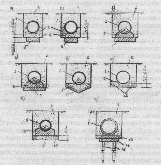
Fig. 2.10. Artificial basis under gravity pipelines: a-gravel-crushed stone; b-flat concrete; in - concrete profiled; d-reinforced concrete profiled; d - crushed stone with waterproof tray; e-gravel and crushed stone; f - concrete with drainage; g-reinforced concrete on stilts; h - pipeline: 2 - backfilling with normal compaction, 3 - filling of enhancement higher degree of compaction, 5 - gravel-crushed stone preparation; 6 – reinforced concrete flat base, 7 - a concrete foundation (I layer) 8 - concrete basis (L layer), 9 - profiled concrete foundation, concrete preparation 10, 11 - water impervious layer (hruntoasfalt), 12 drainage, because cement mortar; 14 - concrete zone, 15 - concrete party.
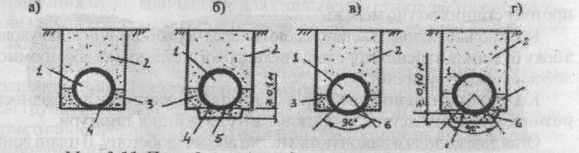
Fig. 2.11. Natural basis for gravity pipelines:
a- ground flat; b - flat with sandy soil preparation, c-ground profiled; d-ground profiled; 1 - Pipeline 2 - filling tranche; 3 - filling with high degree of compaction, 4 - Flat base, 5 - sand bag, 6-profiled basis.
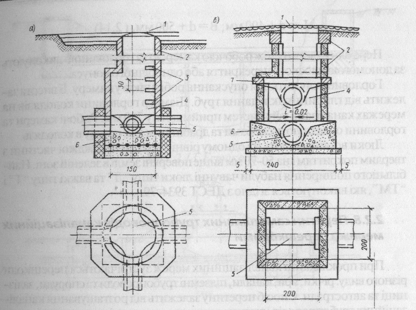
Fig. 2.12. Overlook sewage wells:
a) Round b) Rectangular: and - iron Duke with lid, 2 - neck 3 - clip 4 - working chamber, 5 - Tray 6 - concrete floor, 7 - floor slab.
The main elements of the wells are: base (preparation, plate and tray), the working chamber floor or part of the transition, throat, cover with a hatch. The height of the working chamber is passed, usually at 1800 mm. Dimensions of the camera due to the possibility of work in view, pr cleaning and maintenance.
Diameters of round cells linear wells on household net of acceptance are available depending on the diameter of the largest pipe.
Dimensions of rectangular chambers made by:
- Pipes with a diameter of 700 mm-1000 mm;
- With diameter pipes over 700 mm - length L and width of B are available by the formulas:
The intermediary part between the working chamber and neck performed by using a flat floor or one-sided cone.
Throat is for orlovyna lowing workers in the camera. Its height depends on the depth of laying the pipes. Diameter holes in the wells of sewerage systems in all taken 700 mm. Working chamber staples and throat equip and ladders to pull into the well.
Hatches set flush with the upper roadway paved and 50 ~ 70 mm above the ground in green zone. Most widespreaded iron manhole type "L" and the heavy ones-my "T" and "TM", performed according to GOST 3934-79.
Дата добавления: 2015-09-07; просмотров: 1533;