REQUIREMENTS in the design and construction of the longitudinal profile of sewerage network
Normal hydraulic conditions of sewage network work are provided by not only correct hydraulic calculations, and rules-but it designing its individual elements. When designing projecting of sewage networks must fulfill the following conditions:
1)sewage lines between wells should be lied straight-linely. In places of plumbing direction changes in plane (on turns) or on profiles (when changing the bow) and in places the accession of one or more tube wells should be constructed;
2) the connection of pipes and reservoirs in wells made in the form of open trays made by smooth lines;
3) pipes and channels in the wells need to connect on top of pipes or on water level (Fig. 2.6a, b). In it, as usually recommended connection on top for pipes of different diameters and on water levels at their same diameter;
In cases when the diameter of the pipe at the next area is less than on previous, a combination of pipelines is carried out "on tray" (Fig. 2.6v).
When connecting non-calculating parts, in-block and yard networks to street networks applied connection by scheme "pipe tray-water level" (Figure 2.6h);
4) Calculated velocity 'must grow along collector. Reducing the estimated rate of the stream, but no less than critical, is allowed only after quenching rate in the previous well;
5) where traffic flows should not prevent crosscurrents, beats jet and support. The angle between the underwater and drainage pipes should be not less than 90 °. Allowed flows connections at any angle when installing wells to drop in a duct;
6) filling in streams that join must be aligned water level or be higher than in the main stream, and velocity less than in the main pipe. Connecting of very small tubes, in particular, yard and quarterly, to large reservoirs should be done so that the tray of a small pipe was flush with the surface water in a large tube counting filling.
In parallel with the hydraulic calculation of sewerage network linking pipes make high-rise building and longitudinal profile of the network with regard conditions above. On profile indicated diameters and inclinations of pipes, length of settlement areas, mark the ground and pipe trays and deep wells.
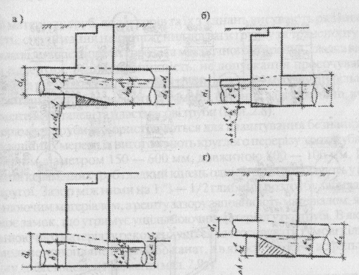
Drawing 2.6.Schemes of pipes connection:
a – on pipes top; b – on water levels; c – on trays; d – tray – water level.
Also, there are shown with obstacles (rivers, channels), ground facilities (railways, roads) and underground utilities, and put data on the pounds and groundwater in view of cuts of holes or hole in the corresponding points of design line profile.
Marks of trays put their pipes with accuracy to 1 mm (with 3 decimal places), marks of the ground and deep wells - up to 1 cm (with two decimal places). In points of pipe size change or drop put their mark two design trays pipes. Horizontal scale profile, as usually taken as equal scale plan and 1:100 vertical.
In Fig. 2.7 shows the linkage pattern altitude and longitudinal profile area network that is shown in Fig. 2.36 of the settlement costs that are listed in Table. 2.3.
Based on the longitudinal profile of the sewerage network and special lied on leveling trace construct more detailed profiles of working drawings, which applied not only settlement but also linear wells. By working drawings performed building of sewage plumbings.
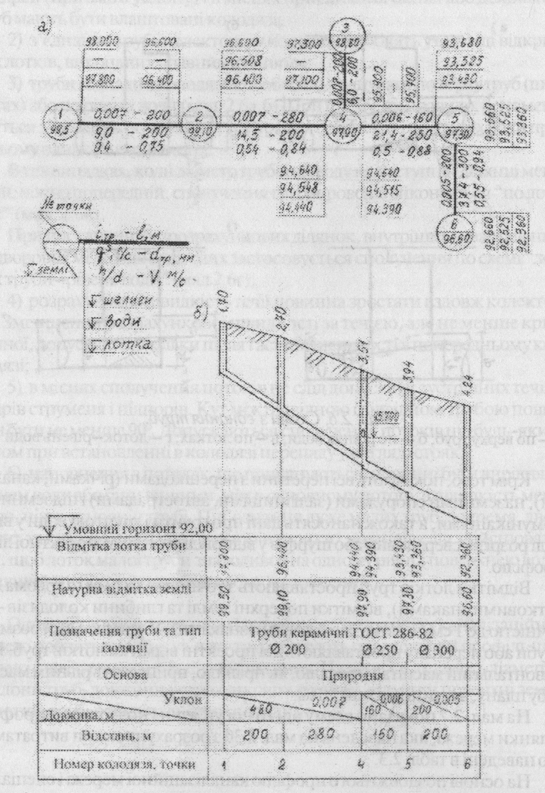
Drawing 2.7. Calculation scheme of high-altitude connection of sewage network (a) and longitudinal profile of collector (b).
Дата добавления: 2015-09-07; просмотров: 1948;