Inertia-type dedusters.
At sharp change of direction of a gas stream movement particles of dust under influence of inertial force will aspire to move in a former direction and further can be allocated from this stream. A lot of dedusters work on this principle. In these dedusters is provided the accelerated movement of particles aside their sedimentation due to change of a direction of a gas stream. Some devices are represented in figure 2.4.
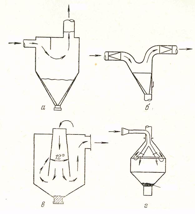
Fig. 2.4 – Inertia-type dedusters: a – chamber with partition; б – chamber with fluent turning of gas stream; в – chamber with expanding cone; г – chamber with deep bunker.
The chamber with partition (2.4а) on efficiency of dust precipitation is similar to the usual sedimentation horizontal chamber, but it has the high hydraulic resistance. Smooth turn in the chamber (2.4б) allows to lower hydraulic resistance.
On fig. 2.4в is shown the chamber, in which the dusty gas stream goes in the beginning downwards on an expanding cone, and then turns on 1800 and it is deduced from above. As a result of it the dust particles are exposed to the additional effort directing them aside of the chamber bunker. The expanding cone allows to lower gradually speed of a gas stream and interferes with secondary dust ablation.
The jalousie-type deduster is represented on fig. 2.5. This device is widely applied to preliminary clearing of gases before cyclones or filters. In it about 90 % of gases partly are cleared of a dust at passage through jalousie, and other gas stream with the caught dust is allocated on clearing in a cyclone.
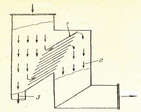
Fig. 2.5 – Jalousie-type dust separator with partial removal of dusty gas stream: 1 – jalousie lattice; 2 – purified gas (nearly 90 volume %); 3 – dusty gas (nearly 10 volume %).
At increasing of speed of gas submission to plates of a lattice the degree of dust catching in jalousie-type deduster in the beginning quickly grows; since speed about 10 m/s growth of speed is slowed. Usually speed of gases in a jalousie-type deduster makes 12-15 m/s. These devices are applied to catching of dust particles more 20 microns.
More effective clearing is achieved in the device on fig. 2.6. The gas stream is given in a wide part of the truncated cone. The surface of this cone has the special holes. At passage through these holes the gas stream changes direction and is released from dust particles, which together with a small part of gases are allocated in a cyclone. At clearing of plenty of gases several similar devices are established in parallel.
If the dusty gas stream collides with any body, the stream flows round it, and the dust particles, possessing the big inertia, hit about a surface of this body and settle on it. This principle is used in the device represented on fig. 2.7. In it some numbers of cores in the form of a half moon are established. Concave surfaces of cores are directed towards to a gas stream. The dust settled on cores is washed off by water.
|
|
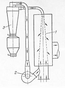 Fig. 2.6 – Jalousie-type dust separator:
1 – cone with slots; 2 – fan; 3 – cyclone
Fig. 2.6 – Jalousie-type dust separator:
1 – cone with slots; 2 – fan; 3 – cyclone
|
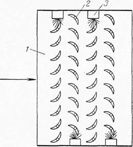
Fig. 2.7 – Inertia-type deduster with repulsing bars: 1 – case; 2 – bars; 3 – irrigation apparatus |
Дата добавления: 2017-11-04; просмотров: 703;