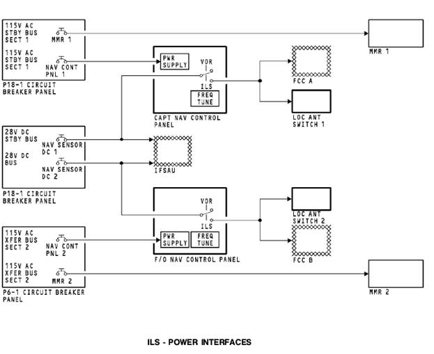
Power Inputs
The P18-1 circuit breaker panel contains the MMR 1 and NAV CONT PNL 1 circuit breakers. The circuit breakers receive 115v ac from the 115v ac standby bus section 1. The circuit breakers supply power to the multi mode receiver 1 and the captain’s NAV control panel.
The P18-1 circuit breaker panel also contains the NAV SENSOR DC 1 and NAV SENSOR DC 2 circuit breakers. The circuit breakers receive 28v dc from the 28v dc standby bus and the 28v dc bus. The circuit breakers send 28v dc to the NAV control panels and to the integrated flight system accessory unit (IFSAU). For the ILS, The IFSAU contains circuits that supply a discrete signal to the LOC antenna switches for operation. The IFSAU uses the 28v dc from the NAV control panel and a discrete signal from the FCC to set the logic to send a discrete signal to operate the LOC antenna switches.
The P6-1 circuit breaker panel contains the NAV CONT PNL 2 and the MMR 2 circuit breakers. The circuit breakers receive 115v ac from the 115v ac transfer bus section 2. The circuit breakers supply power to the first officer’s NAV control panel and the multi mode receiver 2.
When you tune an ILS frequency on the NAV control panels, 28v dc goes to the on-side FCC and LOC antenna switch. The FCC’s use the 28v dc for mode selection. The LOC antenna switches use the 28v dc for operation.
Дата добавления: 2015-04-21; просмотров: 1182;