Calculation of protective earthing
Task 1. Calculate a protective earthing for substation 6/0.4 kV in homogeneous soil.
Initial data. Transformer decreasing substation has two transformers 6/0,4 kV with earthed neutrals on side 0,4 kV and is accommodated in separate one-floor apartment, by dimensions 12 х 20 m.
Not far from station a metallic technological construction was found, partially loaded into soil, which can be used as natural earthing rod having a resistance RE = 20 Ohm to current spreading out.
Solution: A shorting current will be defined for known length of cable lines with voltage 6 kV and Lкл= 65 km, and air Lпл= 60 km.
As vertical single earthing rods will use the bars by length Lст = 5,5 m and diameter d = 18 mm.
The top ends of the bars are connected by means of welding by steel stripe, laid horizontally on depth Нпол = 0,8 m, total length Lпол = 60,5 m and section 4x40 mm.
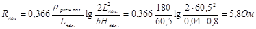
Calculated specific soil resistance for vertical earthing rods (bars) by length 5,5 m Lρроз.ст. = 130 Ohm×m, and for horizontal stripe - flaps Lρроз.ст. = Рроз ·180 Ohm·m. For determination of the resistance of current spreading out from earthing rod will define in advance a shorting current Lзon earth on side 6 kV by following formula:

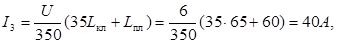
where U is a transformer voltage on the side of high voltage, kV;
Lкл., Lпл. are the lengths of cable and air lines accordingly, km.
Resistance to current spreading out from artificial earthing rod, which will be used as general for electric installations in networks 6 kV and 0,4 kV, will be determined according to ПУЭ-86 requirements.
For earthing rod in homogeneous earth maximum acceptable earthing rod resistance R3 may be computed on most admissible voltage of touch by formula
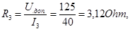
where Uдоп - most admissible touch voltage with taking into account a voltage fall at base support, on which a man stands, equal to 125 V.
Necessary resistance Rн of artificial protective earthing of substation with taking into account an artificial Rз and natural Rе will be defined by formula
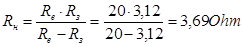 .
.
Calculating artificial earthing, we must select a contour, disposed on perimeter of substation. Vertical bar earthing rods are hammered into soil on distance a = 5,5 m one from another.
From previous disposition of the earthing rods it is evident that at length of horizontal connecting stripe Lпол =60,5 m can be hammered about 11 vertical earthing rods.
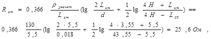
Let’s calculate resistance to spreading out of electric current from single vertical Rcm and horizontal Rпол earthing rod by formulae:
Let’s define a coefficient of use of single bar earthing rod hст and coefficient hпол of stripe usage (using tab. 10.2 in [6]) for relation a/L = 5,5/5,5 = 1 and n =11 pieces.
The coefficient is equal to: hст =0,55, hпол =0,35.
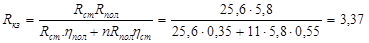
Resistance Rкз to spreading out of electric current from artificial contour earthing rod Rкз may be defined by formula:
 . Ом
. Ом
Calculated resistance Rкз = 3,37 Ohm is less than necessary resistance of artificial protective earthing Rн= 3,69 Ohm, thus the contour satisfies our conditions. Contour consists of 11 vertical steel bars by length 5,5 m, diameter 18 mm, hammered in soil on distance 5,5 m one from another, connected between oneself and with natural metallic construction by steel stripe 4x40 mm, by length 60,5 m.
Дата добавления: 2015-06-10; просмотров: 1180;