Technology and organization of concrete work
Technology of concreting structures are selected according to type of construction, its location on the building or structure, climatic conditions, availability of energy resources, etc.
Foundations and arrays depending on the size, penetration, and their height and other features can be concrete, using the following flow diagrams: a mixture of unloading from a vehicle directly into the casing from the ground or a bridge or overpass mobile (pic. 7.13), with the help of vibratory feeder, vibrating channels , concrete pumps or buckets with taps.

Pic. 7.13. Concreting of the foundation with concrete unloading from a vehicle directly into the formwork:
1 – Concrete Delivery Truck, 2 – vibrating feeder, 3 – vibrating tray, 4 – formwork
Concreting foundation step is performed in three steps. Initially concreted lower level, then to die socket former and then - top of die. In the foundations of the parties cross-section of 0.4-0.8 m height of die free fall concrete is allowed up to 5 m, with the size of the parties of more than 0.8 m - 3 m high concrete slump die with a mixture of equal 4-6 cm to slow and even with some interruptions (1-1.5 h) to avoid squeezing the concrete, laid in stages, through its upper face open.
The foundations, which receive dynamically load concreted in a continuous mode.
Concrete floors, under floor foundation, roads concreted lane width of 3-4 m with the installation of Lighthouse boards. We concreted strip (pic. 7.14) by one, starting from the outermost part of the journey, with gradual approach to travel. Then we concreted the intermediate band. Freed Lighthouse rack swapped to other sites. Sealing lead by screed.

Pic. 7.14. Concreting of preparations and floor:
1 – band concreting, 2 – cross-board, 3 – gauge board, 4 – stakes
Columns concreted decks up to 5 m, and the cross-sectional area less than 40x40 cm and overlapping clips - up to 2 m.
Feed mixtures produce (pic. 7.15) upper, floor, or to the side, with temporary work decks, through the holes, pockets, cut in the formwork columns. Sometimes filing for concrete formwork columns do with removable shields that are installed after concreting of the lower tier. At a height of about 0.7 m from the bottom of the column is cut open inspection ports to monitor the laying of the mixture and further its splicing. Compacted concrete mix, usually vibrators with flexible shaft.
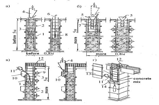
Pic. 7.15. concreting of columns: а – concreting of columns up to 5 m, б – the same, at a height of 5 m, в, г – the same, with thick reinforcement bars; 1 – formwork; 2 – clamp; 3 – fittings; 4 – tub; 5 – loading hopper; 6 – rope; 7 – sectional trunk; 8 – vibration mace; 9 – external vibrator; 10, 14 – pockets; 11 – vibrator with flexible shaft; 12 – reinforcement beams; 13 – removable shield
If the height of columns is more than 5 m mixture is fed through funnel on trunks.
At first concreting of columns (as well as the walls) the lower portion is filled to a height of 100-200 mm cement mortar composition 1:2-1:3 (to avoid the formation of structures in this part of the concrete shells and clusters of coarse aggregate).
Beams and girders concreted, as a rule, simultaneously with the floor slabs. Only for very massive beams (height over 0.8 m) may be allowed as an exception separate concreting. In such cases, workers have few seams below the slab.
Concreting of the runs, beams and slabs should be started 1-2 hours after the concreting of columns and the initial precipitation in their concrete. Sealing of concrete beams and purlins made vibrators. If the beams are reinforced with thick, vibrators are fitted with lugs (vibro- bayonets) or use vibrating combs.
Slabs concreted to full height (thickness) and compacted surface vibrators.
In beams (girders) and plate finned slabs laid mixture, usually at the same time.
The arches of small span (15 m) concreted simultaneously on both sides of the foot to the castle. Concreting of the entire set for each section must be carried out without interruption.
When pouring concrete vaults and arches of the bridge span over 15 meters (pic. 7.16) take measures against the occurrence of cracks due to uneven rainfall cradling and concrete. To this end, the vaults and arches are divided into separate sections (sections), between which leave small gaps of 30-50 cm in width on each plot mixture is fed continuously. Begin laying the mixture from the areas adjacent to the supports. Then, in order to avoid buckling of casing at the top of the arch (arch), the mixture is placed in the castle area. After that, the concrete mix is fed to the ranks sites evenly on both sides of the structure. On the steep sections of arches or vaults to prevent slipping of the concrete mix during vibration, concrete formwork lead by in the way, the outer panels which are increasing in the course of the process.
After 7-14 days after setting the main place of wedges breaks concreted hard concrete mix, creating as it were, and small wedges. Discontinuities are desirable to leave against forest stands or in the nodes curve farms. The wedges are concreted on both sides of the foot to the castle in order to eliminate harmful deformation centering.
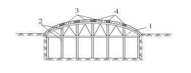
Pic. 7.16. Concreting the span of the arches and arch of the bridge:
1 – formwork, 2 – supporting forest stands, 3 – section of concreting
Дата добавления: 2015-03-07; просмотров: 1059;