FANS and BLOWERS
 Fans are used extensively in the heating and ventilating industry and in most power plants. Their basic design principles fall into two classes: axial-flow fans and centrifugal- or radial-flow fans. Axial-flow fans are basically rotating air-foil sections similar to the propeller of an airplane.
The simplest axial-flow fan is the small electric fan used for circulating air in rooms against very little resistance. Axial-flow fans for industrial purposes are the two-blade or multiblade propeller type, and the multiblade air-foil type. Air enters the fan suction from the left and flows over the rotor with a minimum of turbulence owing to the streamline form of the rotor and drive mechanism. The air stream is straightened by guide vanes located on the discharge side,, thus decreasing the rotational energy of the air by converting it to energy of translation.
The axial-flow fan operates best under conditions where the resistance of the system is low, as in the ventilating field. The axial-flow fan occupies a small space, is light in weight, is easy to install, and handles large volumes of air.
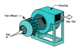
Centrifugal fans may be divided into two major classes:
1) the long-blade or plate-type fan, and 2) the short-blade multi-blade fan. The blades of either type may be pitched toward the direction of motion of the fan, radially, or away from the direction of motion of the fan.
A plate-type radial-blade rotor with double inlet is best suited for handling dirty gases, since there are no pockets in the blades to catch and collect the dirt. The rotor has wearing strips welded to the blades to increase their life. The fan is designed for induced-draft service. The housing of such a fan may have catch plates in the scroll face to collect the fly ash.
Blowers may be divided into two types: 1) rotary, and 2) centrifugal. A common type of rotary blower is the Roots two-lobe blower. Two double-lobe impellers mounted on parallel shafts connected -by gears rotate in opposite directions and at the same speed. The impellers are machined to afford only a small clearance between them and between the casing and impellers. As the lobes revolve, air is drawn into the space between the impellers and the casing, where it is trapped, pushed toward the discharge, and expelled. The air is trapped and discharged in volumes equal to the space between the impellers and casing, and the operation is repeated four times for each rotation of the shaft.
In order to change the volume rate of flow[17] or volume capacity[18] of the blower, the blower speed is changed. The pressure developed by the blower will be whatever is necessary[19] to force the
air through the piping system. The volume of air delivered by the blower will not change appreciably with variations in resistance to flow. Thus, the blower is called a positive-displacement blower.
Note that at a speed of 600 rpm an increase in pressure from 2 to 3 psi increases the power required by 1.5 times, but the capacity remains fairly constant. Care should-be taken in operating any positive-displacement blower. A safety valve or limit valve should be placed on the discharge line to prevent the discharge pressure becoming excessive in case the outlet is fully closed. The limit valve will prevent overloading the discharge line and the driving motor. The advantages of the rotary blower are: 1) simple construction, 2) positive air movement, 3) economy of operation and low maintenance.
Centrifugal blowers and compressors operate on the same principles as centrifugal pumps arid resemble to a marked degree the closed-impeller centrifugal pumps. A single-stage single-suction blower is capable of delivering 15,000 cfm against a pressure 6f 3 psi. The casing or housing is constructed of heavy steel plate, and the impeller is an aluminum-alloy casting. If care is taken in providing the proper drive motor, the overload characteristics of the centrifugal blower will cause no trouble.
For volumes greater than those that can be handled by the single-stage single-suction blower, a single-stage doublesuction blower is used. This blower is capable of supplying 26,000- cfm of air at 60° F and atmospheric pressure against a 54-in. water column or 2 psi.
Дата добавления: 2015-06-17; просмотров: 2110;