Read the text and define recent trends in unneling
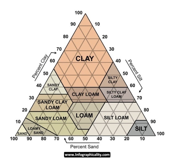
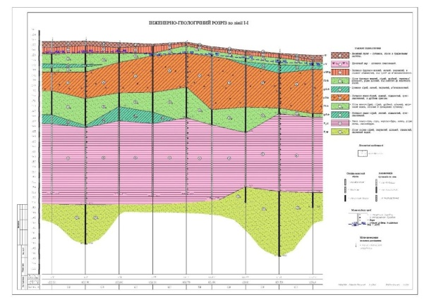
Being a passage excavated in rock or soil, tunnels are the ever-present challenge to civil engineers. Practically tunnels are excavated in various types of underground conditions, from soft ground and weak rocks to hard rock and underwater. Conventional desk studies do not provide sufficient details to assess the exact location of fault zones. Due to unforeseen geological constraints, any tunnel project starts with a comprehensive engineering-geological survey of rock conditions in term of hardness, extent of fracturing, etc. (fig.18.1).
| 
|
| a - Soft ground layers | b - Engineering-geological estimation |
Figure 18.1 View of different geological layers
As a single tunnel may pass through more than one type of rock, it is essential to reduce the risk of facing gas- and water bearing strata in the early stages of tunnelling. Engineers conduct a thorough geologic analysis for selecting the proper tunnelling technologies, and for choosing the type of support to obtain safe tunnel systems.
Tunnel engineers often use the term “driving” for expressing the general idea of tunnel building though construction methods may be very diverse. For instance, tunnelling through loose or soft ground such as sand, sandy loam or clay is very different from tunnelling through hard rock such as granite, basalt, quartzite, or soft rock, such as shale, chalk or sandstone. The builders evaluate the site geology by driving a probe-type tunnel ahead of the tunnel face. It helps to select the construction method.
Tunnelling history started with manual labor using hand digging tools, rapid heating and cooling. Then it advanced to the cut-and-cover method, drill-and-blast method using explosives, and shield tunneling devised by Marc Brunel and James Greathead who constructed two tunnels under the Thames River. More than a hundred years later, the American engineer James Robbins invented the TBM (tunnel boring machine) which is suitable for longer, circular tunnels. It could move forward grinding rock and soil by digging or cutting heads mounted on its rotating front face. The arrangement of their cutting heads matches the site geology and makes TBMs widely used and customized for any tunnel type. Truck-mounted drilling jumbos equipped with several high-speed pneumatic drills with replaceable cutting bits can also work in hard rock, controlled by a single operator. Muck is loaded into tracked cart driven by electric locomotives, which run along narrow-gauge tracks. The gauge in tunnels ranges from 600 to 750 or 900 mm.
| 
|
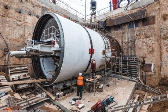
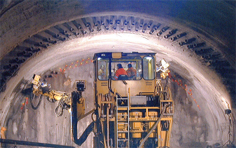
| a – Tunnel excavating started from a vertical shaft. | b - A launch chamber (камера запуска) |
| 
|
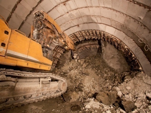
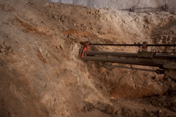
| с – Excavating the calotte ground by a drilling jumbo (открывание калотты буровой кареткой) | d – Drilling holes for placing charges of explosives (бурение шпуров для закладки зарядов) |
Figure 18.2 Stages of tunnel excavation
Generally, tunnel builders use two basic techniques. Passing through strong ground and building smaller tunnels, they use the full-face method excavating the entire tunnel diameter at the same time. Digging a smaller tunnel known as a heading, they normally use the top-heading-and-bench methodusing the individual excavation phases for heading, bench and invert. The heading tunnel helps in assessing the rock stability before moving forward.
As most tunnels are excavated through rock that comprises breaks or pockets of fractured rock, engineers must strengthen tunnel walls and crowns with sprayed concrete, bolts, or a permanent concrete lining.
Tunnel excavating can start with a vertical opening called a shaft (fig. 18.2a). Unlike the actual tunnel, shafts are shorter, and serve for analyzing the bedrock or providing headings for excavating the tunnels. In this shaft, large launch chambers are excavated for assembling TBMs (fig. 18.2b). Alternatively driving may start from a horizontal tunnel or an entry drift. Tunnelling underwater or through mountains normally started from the two opposite ends of the passage.
Hard rock tunneling through mountains involves subdivision of the tunnel cross section into several drifts, and driving them sequentially (fig. 18.3). This excavation method comprises the following phases:
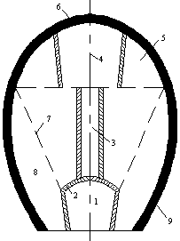
Figure 18.3 Hard-Rock Tunnelling (горный способ проходки тоннеля)
1 – Lower Drift (нижняя штольня); 2 – Temporary Support (временная крепь);
3 – Footway (ходок); 4 – Top Heading (верхняя штольня); 5 – Calotte (калотта);
6 – Lining (обделка); 7 – Middle Drift (средняя штросса);
8 – Side Wall Drift (боковая штросса); 9 – Lining (обделка)
Driving starts from the lower drift (1) with temporary support (2) and vertical or inclined footways (3), dug towards the top heading (4). The next step is to penetrate into the top tunnel sides known as the calotte (fig.18.2c), i.e. driving the top drifts intended for crown lining (5). If the tunnel crown is fractured, it requires supporting immediately after excavation (6). Then the middle drift called the stros (7) is cut, and finally, the sidewall drifts called side strosses (8) are excavated. To prevent water entering in the driven areas, drift miners accommodate a watertight lining made of bolted segments with sealing gaskets. To stabilize soil or fill voids behind the tunnel lining, they may inject grout. The muck is transported out, and the tunnel is given its final lining to support the adjacent ground.
Hard rock tunneling almost always involves the traditional “drill and blast” method, which requires the following phases:
Blasting crew drills a predetermined pattern of blast holes in the rock (fig.18.2d), and places carefully planned charges of explosives into the drilled holes so that they detonate in the right sequence without damaging the adjacent rock. Then the workers are evacuated and the explosives are detonated.
The next phase is removing noxious blast fumes and dust by exhaust ventilation. The workers often use water to control dust after blasting and during drilling. As safety is always the first consideration for blasting crews, the workers enter the tunnel for finding the unexploded charges, and for removing debris dislodged by the blast. Tunnel muck is transported to the entrance where dumper trucks remove it. Then the drift miners smooth the surface of the blasted section by pneumatic drills and hand tools, and repeat the process for advancing the tunnel further through the rock.
Shallow lying tunnels are usually built by the cut-and-cover method within the excavated trench with the necessary ground support, and covering it with backfill. The tunnel may be built of precast archesor in situ concrete and other materials. Once the trench is carefully backfilled, the road workers restore the roadway on top of the tunnel. This technique comprises two basic forms: the bottom-up or caisson wall method and top-down or diaphragm wall method.
A major challenge for tunnelling in soft ground and weak rock is the high groundwater level. When driving is below the water table, it requires very close control. To ensure the face stability. drift miners use either compressed air or TBMs. Excessive groundwater inflow can be suppressed by a temporary lining followed by a final permanent lining made by a liquid concrete called shotcrete that is sprayed on tunnel surfaces.Currently concrete is reinforced by either steel or fiber. When a layer of shotcrete about 7 cm thick is sprayed onto the tunnel walls, it is reinforced by one or two layers of wire mesh placed to it. Alternatively, the shotcrete might be strengthened by adding reinforcing fibers.
As weak rock is prone to collapse and can clog digging equipment, water-saturated ground, boggy ground and quick sand require some stabilization methods such as freezing soft soil or injecting grout into fractured rock. Small pipes are embedded in the ground at intervals, and a refrigerant such as water-and-salt brine or liquid nitrogen, circulating through these pipes, freeze the soil.
| 
|
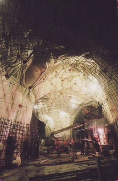
| a - the New Austrian Tunnelling Method (NATM) with wire mesh, rock bolts (Новый Австрийский метод с использованием металлической сетки и анкерных болтов) | b - the New Austrian Tunnelling Method (NATM) with the double layer of tubes installation (Новый Австрийский метод с использованием двойного слоя труб) |
Figure 18.4 the New Austrian Tunnelling Method (NATM)
Tunnelling techniques are largely dependent on rock compressive strength, water and gas pockets, the number of cleavages, etc. Tunnel builders monitor the deformation in weak rocks and provide efficient tunnel support made of shotcrete, wire mesh, rock bolts and lattice girder (fig.18.4). The builders registered this method, based on the inherent rock potential, as the New Austrian Tunnelling Method (NATM). It provides high-performance tunnelling and high levels of safety for underground teams.
Maintaining ground stability during tunnel construction and ensuring structural integrity of the tunnel lining are crucial factors in tunnelling technologies. However, of no less importance is achieving the proper alignment of the excavation path. The global positioning system provides the proper tunnel alignment tunnel by the sensors receiving accurate location data via satellite signals (fig.18.5).Engineers also use laser guidance systems to provide quality control of tunnel alignment by projecting and detecting a laser beam within the tunnel.
To complete the construction of the tunnel, workers install ducts for carrying the cables to provide the safety systems and lightning. Summarizing the opportunities and challenges inherent to building a tunnel, one can take the conclusion that tunnel technologies involve a combination of different methods.
Дата добавления: 2015-01-26; просмотров: 2132;