Guidelines for design of arch and lateral bracing, according to Teich
In the research performed by Teich, a large number of parameters is investigated to determine their influence in the force distribution in the arch. Eventually for all parameters optimal values are determined. Based on these optimal values a design guide is developed that leads to optimal arch design [1]. In this paragraph a brief evaluation of the results of the research is given for each of the following parameters:
- Hanger arrangement
- Number of hangers
- Type of lateral bracing
- Cross section of the arch
- Stiffness of the portal frame
- Arch geometry
Hanger arrangement.The hanger arrangement is of great influence on the stress distribution in the arch. Under perfect conditions the arch is fully supported in plane by the hangers. When a situation arises where some hangers become relaxed, these hangers stop supporting the arch. This could cause global instability. For more about the optimal hanger arrangement see paragraph 2.2.4.2.
Number of hangers.The amount of hangers per arch plane has a significant positive influence on the force distribution in the arches. However this influence gradually decreases. For that reason the number of hangers will not be of decisive influence for the design of the arch. In general it is concluded by Teich [1] that the maximal amount of hangers should not exceed 50 because their efficiency reduces significantly above 50.
Type of lateral bracing.When deciding on the type of lateral bracing the general conclusion can be drawn that trusses have a positive influence on the stability of the arch, along with basket handle type arches. The Vierendeel frame (frame with rigid connections) has less favorable properties, but is easier to erect.
Variable cross-section.Teich investigated the influence of the width, height and plate thickness of the arch along the length of the span. Variable dimensions often result in a complicated production and engineering process. For that reason Teich advises to use variable plate thicknesses. For guidelines and more accurate possibilities for the reduction of the arch cross-section see [1].
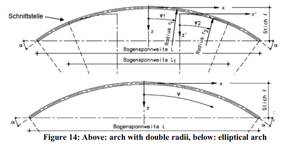
Arch geometry.The form of the arch mainly influences the normal force distribution in the arches. Teich concluded that two specific arch forms have significantly better properties with respect to normal force distribution. The favored forms are shown in Figure 14 and can be described as, elliptical arch and arch with double radii. For both arch forms it is concluded that the optimal ratio between both radii is 1,9.
The height of the arch mainly influences the magnitude of the normal force in the arch and main girder. This is no different from classical arch bridges. For that reason the height of the arch bridge is based upon the experiences with other network arch bridges: 1/5 to 1/7 of the span length. The advantage of this approach is that an aesthetical component is automatically included.
Main girder
The main girder transfers the loads from the deck to the hangers and counteracts the horizontal thrust that is created by the arches. The intermediate distance between the hangers dictates the required bending stiffness. Because the amount of hangers in network arches is a lot higher than in arch bridges with vertical and diagonal bracing, the intermediate distance is shorter. This results in a more slender main girder.
In the existing network arches, the main girder has been designed as: concrete slab, composite girder, steel I- and box-girder. All these designs have proven to be functional. But when considering execution, hanger connections and efficient material use, the best solution for a main girder would be a steel profile [7]. Depending on the type of loading, a suitable cross section can be selected. For instance, in single track railway bridges no torsional rigidity is necessary, so an I-section is sufficient.
The stiffness of the main girder hardly influences the overall force distribution in the bridge. Geiβler et al. [7] recommend a stiffness ratio of EIarch/EImaingirder = 1/8 .. 1/10. Teich uses a stiffness ratio of 1/3 in his research. This large difference in ratio supports the statement that main girder stiffness influences the overall force distribution.

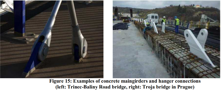
To connect the hangers to the main girder, stiffening plates or cable anchorages (see Figure 15) should be incorporated in the design. An efficient solution is to connect the hangers directly to the web of the I- or box-section as is shown in Figure 15. This of course has aesthetic consequences, but eliminates the need for extra stiffening plates (diaphragms).
Deck.The deck should accommodate pedestrian, bicycle, road or railway tracks. In some cases an additional service track is also required. The service track could also be placed on top of the main girder or outside the arch planes by means of consoles connected to the main girder. This leads to a reduction in deck width with significantly lower bending moments as a result. For examples and guidelines for the design of a bridge deck, reference is made to [4], especially for railway bridges.
In general the heavier bridge decks are preferred [4], especially for road bridges. This is because of the better sound and fatigue properties. Disadvantages are the extra weight, construction time and the specific disciplines required. Eventually all parameters should be considered to find the optimal deck structure.
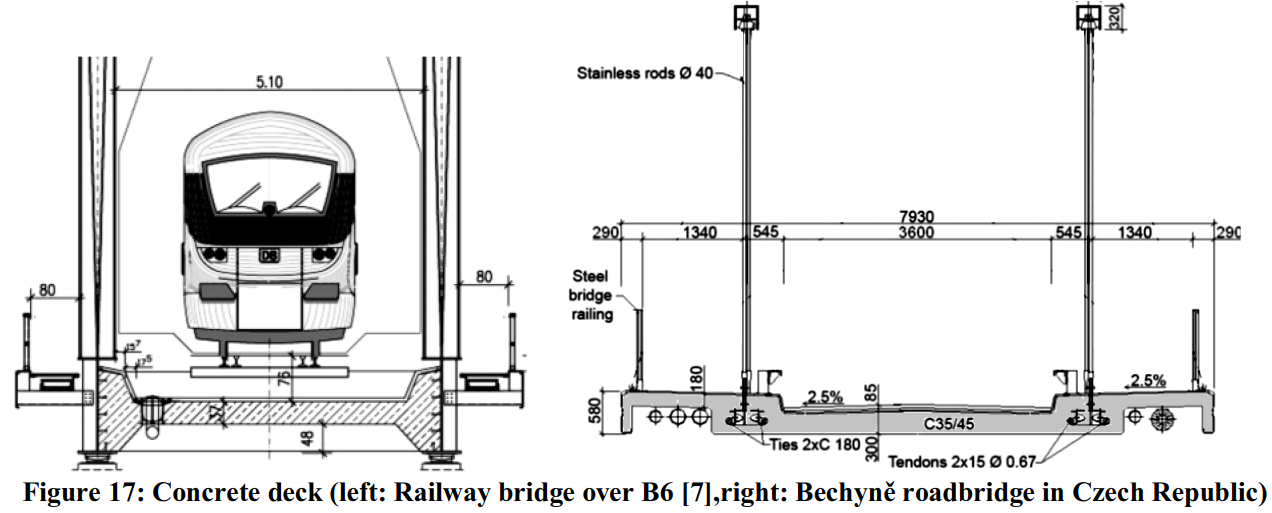
Concrete deck.According to Per Tveit the most economic network arch is one with a longitudinally prestressed concrete slab (see Figure 17 right). In this design the deck and main girder are merged together and the tensile force is taken by the pre-stressing tendon. The main disadvantage of a full concrete deck is the need for temporary supports and scaffolding. A solution is to apply a full concrete deck in combination with a steel main girder as is shown in Figure 17 (right). A more exceptional method is used in the construction of the Troja bridge in Prague. Here precast and prestressed beams are used 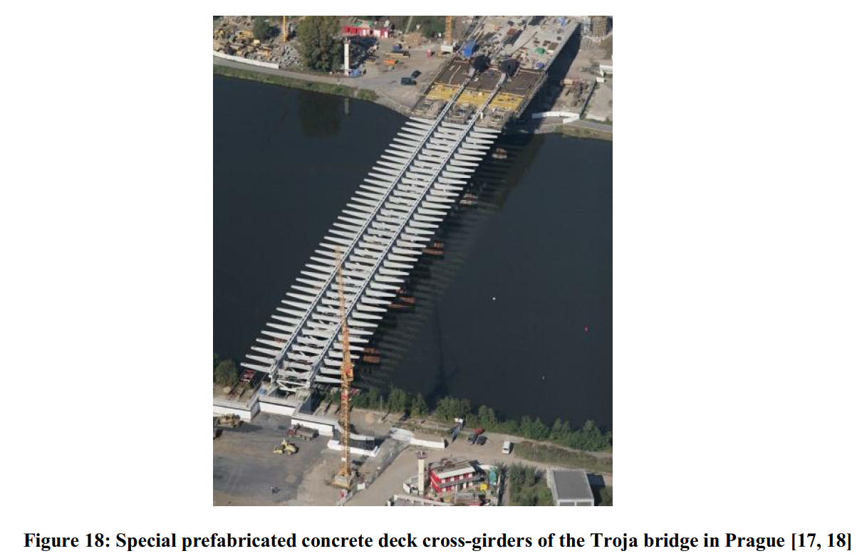
as cross girders in combination with a prestressed thin deck slab, see Figure 18.
Composite deck

When time, deck-height, and weight are of minor importance, a composite deck can be applied. The advantage of this deck configuration is that the additional weight causes better noise reduction properties and also could prevent the relaxation of hangers. The disadvantage is that extra time is required for the casting and hardening of the concrete.
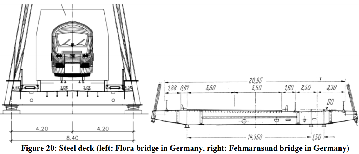
Steel deck
The main advantage of a steel deck is the short erection time and the possibility for prefabrication. A large weight reduction is achieved compared to concrete bridge decks. Disadvantages are: higher noise production, fatigue sensitivity of the deck and the extra maintenance when compared to concrete decks.
The deck plate is composed as an orthotropic deck with cross girders spaced every 2,5m. The tension force of the arches is taken by steel beams in longitudinal direction. When a full steel deck is applied, provisions for noise reduction have to be made.
Hangers
When considering the hangers, two main design considerations must be made; hanger type and hanger arrangement. Both aspects have a large influence on the structural behavior, but also the costs and aesthetics of the bridge.
Hangertype
Based on the literature reviewed, three different hanger types are assessed in this paragraph. For each of the hanger types the following aspects are considered:
- Costs
- Connection type
- Aestethics
- Vibrational effects
Дата добавления: 2017-04-24; просмотров: 2024;